background image

       WACHS TRAV-L-VAC 300

11

 SECTION IV

                             SET-UP AND OPERATION

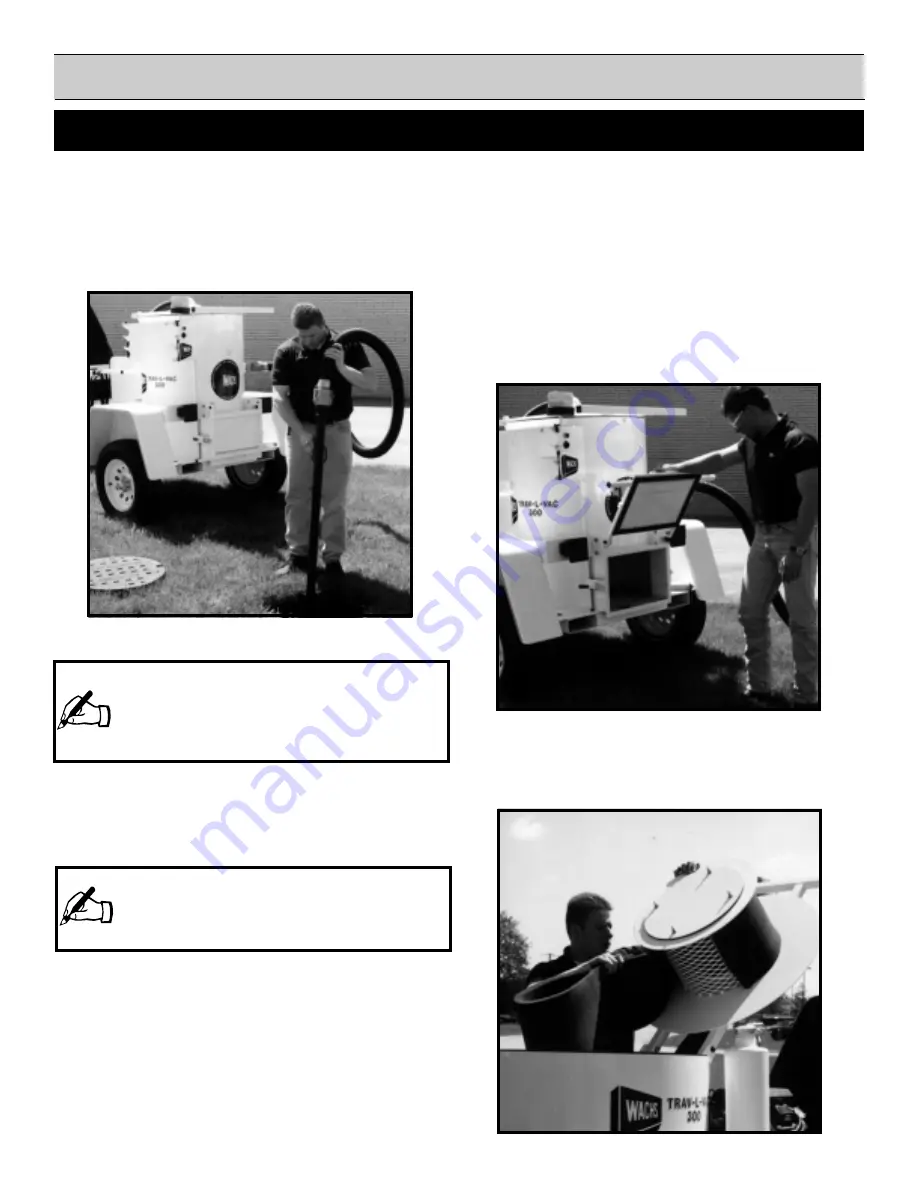
extract debris until valve box is empty or until holding
tank is full. (Fig. 3)

5. If the unit fills with liquid to its limit, the high liquid level

switch will automatically shut off the engine. Before
restarting unit, the holding tank must be drained. If this
is not done, unit will not start.

6. After the vacuum operation is over, run engine for several

minutes to clear out any water which may have reached
the blower.

7. Consult the manufacturer for special operating sugges-

tions concerning use in freezing weather.

TLV DUMPING PROCEDURES:

Liquids:

1. Shut down engine.

Figure 3

NOTE:  

If a clog occurs, shake suction hose. If clog

remains, open the vacuum diverter valve to remove
vacuum from suction hose. Disconnect the hose
from the TLV. Either use a ram to dislodge clogged
debris or reverse suction hose ends.

NOTE:  

If removing heavier or solid debris, the high

liquid level switch 

may not

 cause the unit to shut

down. Periodically inspect the holding tank to avoid
over filling.

Figure 4

2. Position vacuum system over designated dumping area.

3. If the material collected is primarily liquid, the holding

tank drain plug should be used to remove holding tank
contents.

4. Once liquid has drained, open dump gate and remove

any remaining debris. ( Fig. 4)

5. Clean primary filter prior to next use. Filter can be

cleaned with only water, however, mild soap and water
are recommended if possible. ( Fig. 5)

TLV DUMPING PROCEDURES (CONT.):

Solids:

Figure 5

Summary of Contents for TRAV-L-VAC 300

Page 1: ...L VAC 300 TRANSPORTABLE VACUUM SYSTEM MODEL TLV 300 PIPE VALVE MAINTENANCE EQUIPMENT Model TLV 300 Ser No E H WACHS COMPANIES 100 Shepard St Wheeling Il 60090 Patent Pending E H Wachs Company 600 Kni...

Page 2: ......

Page 3: ...5 IV Installationprocedures 6 SETUP OPERATINGPROCEDURES I Beforedeparturetojobsite 7 II Trav L Vacsetupprocedure 7 III Trav L Vacoperatingprocedure 7 9 IV Liquiddebrisremoval 10 V Soliddebrisremoval 1...

Page 4: ...maximum capacity 345 CFM 9 77 cmm 3600 RPM with 14 355 6 mm Hg 15 813 FPM 4 819 8 cmm air velocity through 2 50 8mm diam eter inlet FILTRATION Primary drum filter with 2 50 8 mm of polyethylene foam...

Page 5: ...must be worn while operating or working near this tool CAUTION Personal hearing protection is recommended when operating or working near this tool 4 KEEP CLEAR OF ROTATING PARTS Keep hands arms and f...

Page 6: ......

Page 7: ...WACHS TRAV L VAC 300 7 SECTIONIV SET UP AND OPERATING PROCEDURES...

Page 8: ...length to connect the tail lights 082 083 18 Strip the ends of the trailer wires 1 2 for proper connection 19 Feed the trailer wires through the upper slots on the fender braces 20 Push the stripped b...

Page 9: ...WACHS TRAV L VAC 300 9 SECTION IV SET UP AND OPERATION INSTALLATION DIAGRAM...

Page 10: ...aphs Section TRAV L VAC 300 SET UP PROCEDURE 1 Position TLV system near work area 2 Connect coupling of suction hose to coupling on vacuum inlet port Figure 1 3 Connect coupling on suction hose to cou...

Page 11: ...TE If a clog occurs shake suction hose If clog remains openthevacuumdivertervalvetoremove vacuum from suction hose Disconnect the hose from the TLV Either use a ram to dislodge clogged debris or rever...

Page 12: ...xcavating water always be sure to submerge the suction tube completely 2 If debris is packed in the bottom of the valve box rotate the suction tube assembly back and forth to break up debris 3 For sol...

Page 13: ...WACHS TRAV L VAC 300 13 SECTIONV MAINTENANCE...

Page 14: ...quivalent FILTER MAINTENANCE SCHEDULE DAILY Clean primary filter WEEKLY Clean pre filter NOTES Frequency of cleaning will increase under severe oper ating conditions All filters are washable with mild...

Page 15: ...ssive debris build up Check lug nuts and fasteners for tightness Tighten as necessary MONTHLY Check blower drive belts for proper tension frayed or cracked condition Adjust or replace as needed Check...

Page 16: ...WACHS TRAV L VAC 300 16 SECTIONV MISCELLANEOUS CHARTS AND GRAPHS...

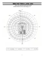
Page 17: ...WACHS TRAV L VAC 300 17 TRAV L VAC 300ACOUSTIC EVALUATION SOUND DECIBLE LEVEL DIAGRAM 10 FT...

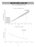
Page 18: ...WACHS TRAV L VAC 300 18 TRAV L VAC 300PERFORMANCE CHARTS...

Page 19: ...WACHS TRAV L VAC 300 19 BILL OF MATERIAL...

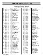
Page 20: ...1 2 HHCS 7 90 071 20 6 3 8 16 x 2 HHCS TRAV L VAC 300 BILL OF MATERIAL PART NO 59 000 01 59 401 01 REF PART NO QTY DESCRIPTION REF PART NO QTY DESCRIPTION 01 59 300 01 1 TLV FRAME 02 59 302 01 1 BLOW...

Page 21: ...WACHS TRAV L VAC 300 21...

Page 22: ...0 x 1 HHCS 14 90 051 07 2 1 4 20 x 3 4 HHCS 15 90 055 01 7 1 4 20 HEX NUT 16 90 055 52 7 1 4 LOCK WASHERS 17 90 055 53 6 1 4 FLAT WASHERS 21 90 065 52 4 5 16 FLAT WASHERS 22 90 065 51 7 5 16 18 LOCK W...

Page 23: ...1 2 x 3 1 2 031 59 031 00 1 NIPPLE 2 1 2 x 7 032 59 032 00 1 NIPPLE 2 x CLOSE 050 62 050 00 1 BLOWER AIR 051 62 051 00 1 SILENCER AIR 052 62 052 00 1 VALVE KNUCKLE 058 62 058 00 1 TEE 2 1 2 060 62 06...

Page 24: ...ber and a brief description of problem or work to be done or estimated All repair work done at our plant will be estimated and the customer advised of cost and time required to complete repair WARRANT...

Reviews: