


WACHS TRAV-L-VAC 300
8
SECTION IV
SET-UP AND OPERATION
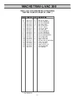
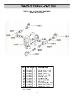
TRAILER PACKAGE ASSEMBLY:
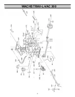
NOTE: REFER TO INSTALLATION DIAGRAM
1.Bolt fender braces (076) to dump gate sides by using 3/8-16 x 3/4
HHCS, 3/8 lock washers and 3/8-16 hex nuts.
2.Secure the fenders (075) to the fender braces by using 3/8-16 x 3/
4 HHCS, 3/8 lockwashers and 3/8-16 hex nuts. Align the holes in
the fender with the holes in the TLV frame (01).
3.Position the axle (078) under the frame with the torsion arms
trailing toward the dump gate. The axle is bolted to the fame
through the holes closest to the tongue side of the frame.
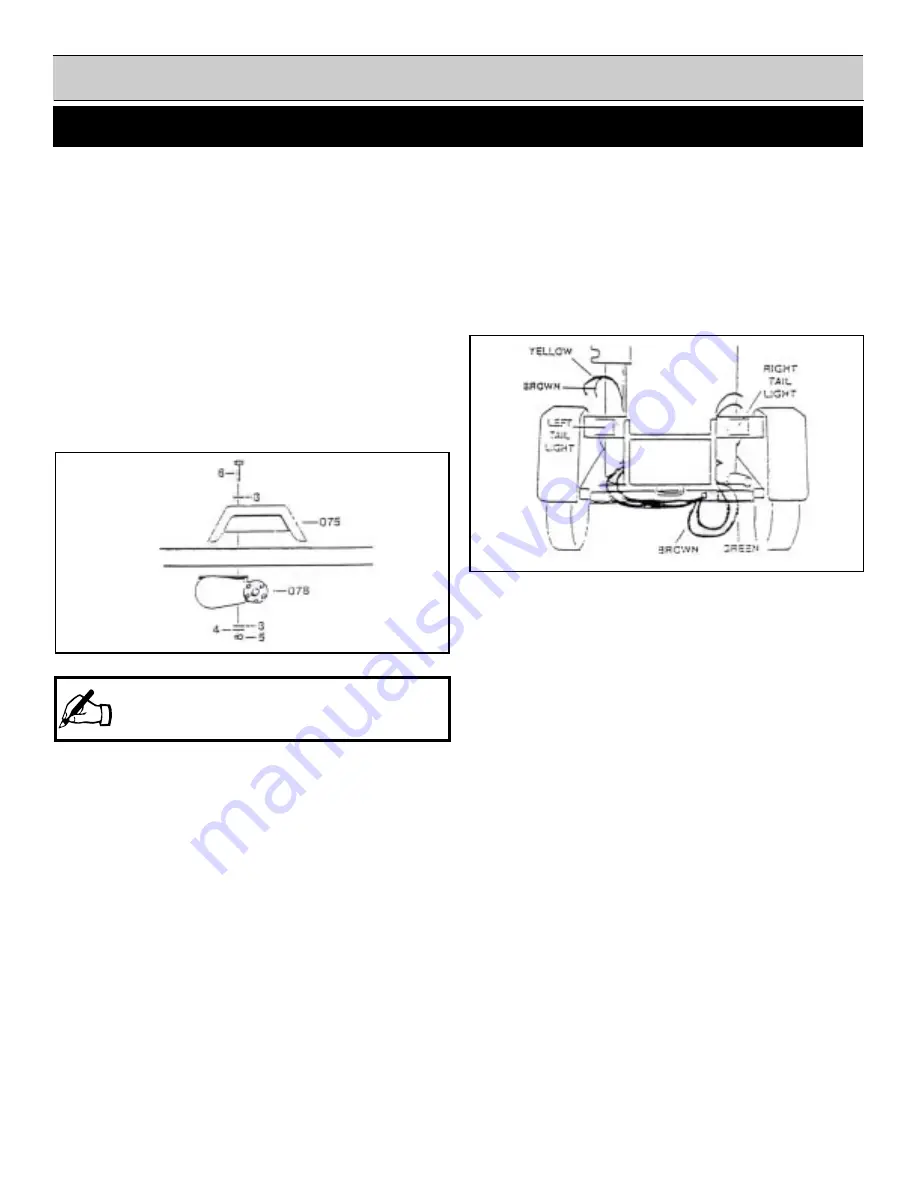
4.Join the fenders to the axle, through the frame, by using 1/2-13 x 4-
1/2 HHCS (6), 1/2 flat washers (3) 1/2 lock washers (4) and 1/2-
13 hex nuts (5). (Fig. 1)
12.Pull the green and brown wires up through the conduit directly
above the exit hole. The green and brown wires are for the RIGHT
tail light. (Fig. 2)
13.The yellow and brown wires are strung along the TLV frame
below the dump gate. The yellow and brown wires are for the
LEFT tail light. (Fig. 2)
14.Holes are predrilled in the frame to secure the wires using wire
clamps and #10 self drilling hex head screws.
15.Pull the yellow and brown wires up through the conduit and out
through the hole near the fender brace.
16.Remove the slack from the trailer wires and secure them to the
fender braces with the supplied adhesive wire clips.
17.Cut the trailer wires allowing for sufficient length to connect the
tail lights (082 & 083)
18.Strip the ends of the trailer wires 1/2" for proper connection.
19.Feed the trailer wires through the upper slots on the fender braces.
20.Push the stripped brown ends into the hole on the trailer lights
marked tail.
21.Push the stripped green and yellow ends into the hole on the
trailer lights marked stop.
22.Bolt the trailer lights to the fender braces using 1/4-20 hex nuts
and 1/4 lock washers.
23.Check that the lights are working properly.
24.Attach your license plate through the holes on the LEFT fender
brace. Apply the amber side markers on each side of the TLV 300
frame.
NOTE: Ensure
that the axle is mounted perpendicular to
the direction of travel. A misaligned axle will decrease
tire life and will not tow satisfactorily.
5.Place the center caps (081) in the rim and mount the wheels
(079) on the axle using the lug nuts (080).
6.Pull the wire harness (084) wires through the hole at the back of
the tongue receiver. Do not remove the protective loom from the
wires.
7.Insert tongue (077) into the receivers. Be sure to pull the
excess wire with the tongue to avoid damage.
8.Line up the holes in the tongue with the holes in the receiver.
Secure the tongue in place with the supplied pull pins (090)
and keeper pins.
9.Attach the jack (103) to the tongue using the supplied snap ring
(104).
10.Pull the trailer wires through the holes under the TLV frame
until they come out the back corner, beneath the drain plug.
11.In addition to pulling the trailer wires through the holes, adhesive
wire clips (*106) are provided to keep the wiring secured to the
frame.
(Fig. 1)
(Fig. 2)
Summary of Contents for TRAV-L-VAC 300
Page 2: ......
Page 6: ......
Page 7: ...WACHS TRAV L VAC 300 7 SECTIONIV SET UP AND OPERATING PROCEDURES...
Page 9: ...WACHS TRAV L VAC 300 9 SECTION IV SET UP AND OPERATION INSTALLATION DIAGRAM...
Page 13: ...WACHS TRAV L VAC 300 13 SECTIONV MAINTENANCE...
Page 16: ...WACHS TRAV L VAC 300 16 SECTIONV MISCELLANEOUS CHARTS AND GRAPHS...
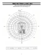
Page 17: ...WACHS TRAV L VAC 300 17 TRAV L VAC 300ACOUSTIC EVALUATION SOUND DECIBLE LEVEL DIAGRAM 10 FT...
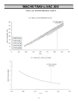
Page 18: ...WACHS TRAV L VAC 300 18 TRAV L VAC 300PERFORMANCE CHARTS...
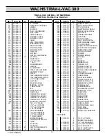
Page 19: ...WACHS TRAV L VAC 300 19 BILL OF MATERIAL...
Page 21: ...WACHS TRAV L VAC 300 21...


