6-4
BA 1001/1501/2001 us – Edition 3.3 * * 12001b610.fm
Technical data (1001 – 1501)
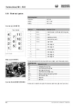
6.10 Electrical system
Fuse box (up to AC000101)
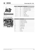
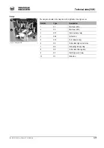
Relays (up to AC000101)
The relays are located in the relay box under the control stand, next to the swiveling console
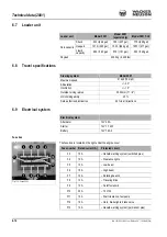
Fuse box (from AB150001H/150002D)
The fuse box is located on the right of the machine under the engine cover (see arrow).
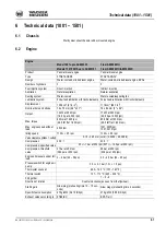
Electrical system
Alternator
12 V 40 A
Starter
12 V 1.1 kW
Battery
12 V 45 Ah
Fig. 103: Fuse box
Travel direction
Fuse no.
Rated current (A) Protected circuit
1
30 A
– Cutoff solenoid, cutoff solenoid time lag relay
2
7.5 A
– Horn
3
7.5 A
– Alternator governor
4
7.5 A
– Solenoid valve pump
5
7.5 A
– Light switch
6
– Not assigned
7
– Not assigned
8
7.5 A
– Indicator lights
9
– Not assigned
10
– Not assigned
11
– Not assigned
Fig. 104: Relays
K6
K9
K30
F12
K8
K7
K7.1
A3
Switching relay
no.
Protected circuit
K 6
– Preheating time lag relay
K 8
– Cutoff solenoid time lag relay
K 7
– Start high-current relay
K 9
– Cutoff solenoid switching relay
K 30
– Relay for parking brake warning buzzer
K 7.1
– Start interlock relay
A 3
– Regulator
F12
– Main fuse

