OM 25-3503 us – Edition 4.1 * 2503_3503b530.fm
5-21
Maintenance
Reducing tension
• Draining grease in a way different from the one described below is very dangerous.
Also bear in mind the safety instructions on this page.
☞
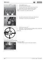
Slowly open the lubricating valve
A
by 1 turn to allow the grease to flow out.
☞
Place a suitable container underneath to collect the grease
➥
The grease flows out of the groove of the lubricating valve
☞
Retighten lubricating valve
A
☞
Check the tension is correct by starting the engine, letting it run at idling speed and
slowly performing forward and reverse machine travel and switching it off again
☞
Check the tension of the tracks again
➥
If it is not correct:
☞
Adjust again
Environment!
Use a suitable container to collect the grease as it flows out and dispose of it in
an environmentally friendly manner.
Maintenance of joint rod (lifting eye) and load hook
Wear of joint rod (lifting eye)
Immediately replace lifting eyes with inadmissible wear (for example if they are beyond the
max. tolerance), damage, deformations, surface cracks and corrosion.
The nominal size must not be worn more than 5 % (max. tolerance). Measurement can be
performed with the accuracy of a slide gage.
Welding is prohibited!
Load hook wear
Have load hooks (Powertilt, Powertilt for Easylock) with inadmissible wear (for example if
they are beyond the max. tolerance), damage, deformations, surface cracks and corrosion
immediately replaced by a Wacker Neuson service center.
The nominal size must not be worn more than 10 % (max. tolerance). Measurement can
be performed with the accuracy of a slide gage.
Welding is prohibited!
If the spring mechanism of snap link
C
does not automatically close any more, stop work-
ing with the load hook and have the error repaired by a Wacker Neuson service center.
Fig. 287: Releasing grease
A
A
B
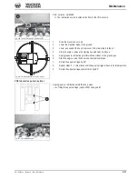
Fig. 288: Lifting eye joint rod (symbolic representation)
Joint rod (lifting eye)
Nominal size A
Max. tolerance B
2503
32 mm (1 1/4 in)
33.6 mm (1 3/8 in)
3503 up to WNCE0307JPAL00239
32 mm (1 1/4 in)
33.6 mm (1 3/8 in)
3503 from WNCE0307JPAL00240
30 mm (1 1/8 in)
31.5 mm (1 1/4 in)
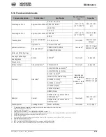
Fig. 289: Powertilt load hook (symbolic representation)
C
A
B
C
Load hook
Nominal size A Max. tolerance A Nominal size B Max. tolerance B Nominal size C Max. tolerance C
2503/3503
105 mm (4 1/8 in) 115.5 mm (4 1/2 in) 32 mm (1 1/4 in) 28.8 mm (1 1/8 in) 30 mm (1 1/8 in) 33 mm (1 1/4 in)
Summary of Contents for 2503
Page 12: ...I 10 OM 25 3503 us Edition 4 1 Ba2503_3503us4_0SIX fm Index...
Page 40: ...1 28 OM 25 3503 us Edition 4 1 2503_3503b110 fm Introduction...
Page 182: ...4 8 OM 25 3503 us Edition 4 1 2503_3503b410 fm Malfunctions...
Page 230: ...5 48 OM 25 3503 us Edition 4 1 2503_3503b550 fm Wartung...
Page 250: ...6 20 OM 25 3503 us Edition 4 1 2503_3503b610 fm Technical datac 2503 3503 long short stick...
Page 252: ...6 22 OM 25 3503 us Edition 4 1 2503_3503b610 fm Technical datac...


