wc_tx003152gb.fm
113
E 1100 / HSH 350
Genset Maintenance
Continued from the previous page.
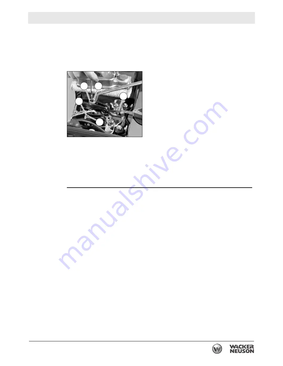
7. Check valve clearances with feeler gauge
(g)
.
Note:
The clearance should be 0.10mm.
8. If valve clearances require adjustment, loosen screw
(h)
and turn the hexagon
nut
(i)
until the feeler gauge can be pulled through with just slight resistance
when the screw
(h)
is retightened.
9. Install a new gasket
(e)
.
10.Reinstall the cylinder head cover.
11.Reinstall parts previously removed.
Note:
Be sure to replace the rubber cap
(f)
.
12.Briefly test run the engine and check the cover for leaks.
Result
The valve clearances have been adjusted.
wc_gr009565
g
h
h
i
i
Summary of Contents for 5000620172
Page 19: ...E 1100 Safety Information wc_si000628gb fm 19 Notes ...
Page 20: ...Labels E 1100 20 wc_si000629gb fm 2 Labels 2 1 Label Locations wc_gr009588 ...
Page 105: ...ghi_tx001153gb fm 105 E 1100 Maintenance ...
Page 122: ...Technical Data E 1100 122 wc_td000476gb fm 10 5 Dimensions cm in wc_gr008706 ...
Page 133: ...wc_tx001673gb fm 133 Fuji Temperature Controller ...
Page 134: ...wc_tx001673gb fm 134 Fuji Temperature Controller ...
Page 151: ...E 1100 Schematics wc_tx001908gb fm 151 11 3 Burner System Circuit ...
Page 152: ...Schematics E 1100 152 wc_tx001908gb fm 11 4 Circulation System Circuit ghi_gr005662 ...
Page 153: ...E 1100 Schematics wc_tx001908gb fm 153 11 5 Rewind System Circuit ...
Page 158: ...Schematics E 1100 158 wc_tx001908gb fm 11 10 Genset DC Wiring Diagram ...
Page 160: ......
Page 161: ......


