wc_tx001903gb.fm
52
Operation
E 1100
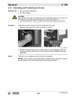
4.16
Preheating the HTF
NOTICE:
Starting the machine with frozen or partially frozen Heat Transfer Fluid
(HTF) will permanently damage the pumps. Preheat the HTF when ambient air
temperature is below -26°C (-15°F).
Requirements
HTF reservoir full
Machine powered up
Procedure
Follow the procedure below to preheat the HTF.
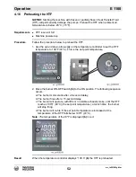
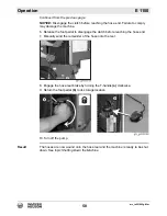
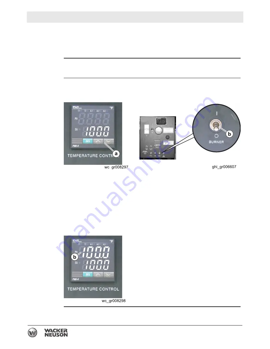
1. Use the up and down arrows
(a)
on the temperature controller to set the HTF
temperature to 100°F (40°C). This is the set point temperature.
2. Move the burner ON-OFF switch
(b)
to the ON position. The following sequence
occurs:
a. The burner motor starts after a 5-second delay.
b. The burner fires after a 15-second delay.
c. The burner will operate, with little or no visible exhaust smoke, until the HTF
reaches 100°F (40°C) (the set point temperature); at which time, the burner
will stop firing.
d. The burner will re-fire if the set point temperature is increased or the
temperature of the HTF falls below 100°F (40°C).
Note:
The temperature of the HTF is displayed
(b)
in red.
Result
When the temperature controller displays “100.0”
(b)
the HTF is preheated.
Summary of Contents for 5000620172
Page 19: ...E 1100 Safety Information wc_si000628gb fm 19 Notes ...
Page 20: ...Labels E 1100 20 wc_si000629gb fm 2 Labels 2 1 Label Locations wc_gr009588 ...
Page 105: ...ghi_tx001153gb fm 105 E 1100 Maintenance ...
Page 122: ...Technical Data E 1100 122 wc_td000476gb fm 10 5 Dimensions cm in wc_gr008706 ...
Page 133: ...wc_tx001673gb fm 133 Fuji Temperature Controller ...
Page 134: ...wc_tx001673gb fm 134 Fuji Temperature Controller ...
Page 151: ...E 1100 Schematics wc_tx001908gb fm 151 11 3 Burner System Circuit ...
Page 152: ...Schematics E 1100 152 wc_tx001908gb fm 11 4 Circulation System Circuit ghi_gr005662 ...
Page 153: ...E 1100 Schematics wc_tx001908gb fm 153 11 5 Rewind System Circuit ...
Page 158: ...Schematics E 1100 158 wc_tx001908gb fm 11 10 Genset DC Wiring Diagram ...
Page 160: ......
Page 161: ......


