wc_tx001903gb.fm
53
E 1100
Operation
4.17
Initiating the HTF Flow
Requirements
Heat Transer Fluid (HTF) preheated. See Topic
Preheating the HTF
Hand protection
Note:
If you are using accessories, see Chapter “Accessories”.
Procedure
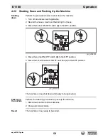
Follow the procedure below to initiate HTF flow.
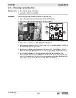
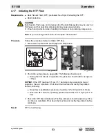
1. Move the Pump ON-OFF switch
(a)
to the ON position.
v
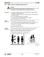
2. Check the pump pressure gauge
(b)
. The following should occur:
During the first minute of operation, the pressure should build to as high as
170 psi.
NOTICE:
If the HTF reaches 170 psi (11.7 bar) after only a second or two of
operation, there is a problem. Shut down the machine and rectify the problem
before continuing.
Once flow is established, pressure should be: 125–140 psi (8.6–9.6 bar).
When the HTF is warm, operating pressure should be: 90–110 psi (6.2–7.6
bar).
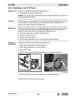
3. Check the HTF flow indicator
(c)
. The flow indicator should be spinning. If it is
not, there is a problem. Shut down the machine and rectify the problem before
continuing.
Result
HTF is now flowing.
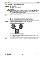
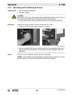
CAUTION
Burn hazard. The hoses and components of the plumbing system may be very hot.
Hot hoses and hot plumbing components may cause severe burns.
f
Wear hand protection when handling hot hoses or hot plumbing components.
wc_gr008696
a
wc_gr008697
b
c
Summary of Contents for 5000620172
Page 19: ...E 1100 Safety Information wc_si000628gb fm 19 Notes ...
Page 20: ...Labels E 1100 20 wc_si000629gb fm 2 Labels 2 1 Label Locations wc_gr009588 ...
Page 105: ...ghi_tx001153gb fm 105 E 1100 Maintenance ...
Page 122: ...Technical Data E 1100 122 wc_td000476gb fm 10 5 Dimensions cm in wc_gr008706 ...
Page 133: ...wc_tx001673gb fm 133 Fuji Temperature Controller ...
Page 134: ...wc_tx001673gb fm 134 Fuji Temperature Controller ...
Page 151: ...E 1100 Schematics wc_tx001908gb fm 151 11 3 Burner System Circuit ...
Page 152: ...Schematics E 1100 152 wc_tx001908gb fm 11 4 Circulation System Circuit ghi_gr005662 ...
Page 153: ...E 1100 Schematics wc_tx001908gb fm 153 11 5 Rewind System Circuit ...
Page 158: ...Schematics E 1100 158 wc_tx001908gb fm 11 10 Genset DC Wiring Diagram ...
Page 160: ......
Page 161: ......


