ghi_tx001153gb.fm
97
E 1100
Maintenance
7.8
Filling the HTF Reservoir
Requirements
Genuine Wacker Neuson Heat Transfer Fluid (HTF), or
Dowfrost HD 50 Heat Transfer Fluid
Machine positioned on a level surface
NOTICE:
Use only factory-recommended HTF. Failure to do so may damage the
machine.
Background
The procedure for routine filling of the HTF reservoir differs slightly from that when
a low level fault is encountered. If your machine has experienced a low level fault,
see topic
Resetting a Low HTF Fault
.
Procedure
Follow the procedure below to fill the HTF reservoir.
1. Move the burner switch to the OFF position.
2. Move the Pump switch to the OFF position.
3. Locate the fill hose under the hose reel.
4. Clean the fill hose and place the open end into a container full of HTF.
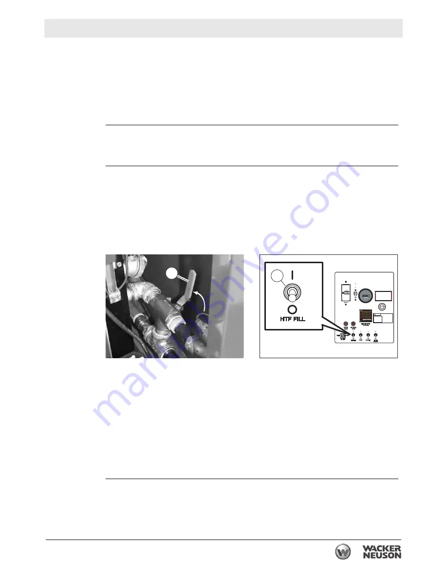
5. Move valve #2 to the fill position (valve handle pointing up).
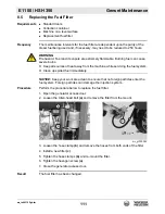
6. Move the HTF fill switch
(a)
to the ON position. HTF will flow from the supply
container to the machine. Watch the HTF reservoir sightglass. When the HTF
level is between the MIN and MAX, move the HTF fill switch to the OFF position.
NOTICE:
Do not overfill the HTF reservoir. Doing so may damage the machine.
7. Remove the fill hose from the HTF container and allow any HTF within the hose
to drip back into the container. Cap the fill hose if a cap is provided.
8. Move the fill hose to its storage location under the hose reel.
9. Move valve #2 to the normal operating position (valve handle parallel with
piping).
Result
The HTF reservoir has now been filled.
wc_gr008459
2
wc_gr008460
a
Summary of Contents for 5000620172
Page 19: ...E 1100 Safety Information wc_si000628gb fm 19 Notes ...
Page 20: ...Labels E 1100 20 wc_si000629gb fm 2 Labels 2 1 Label Locations wc_gr009588 ...
Page 105: ...ghi_tx001153gb fm 105 E 1100 Maintenance ...
Page 122: ...Technical Data E 1100 122 wc_td000476gb fm 10 5 Dimensions cm in wc_gr008706 ...
Page 133: ...wc_tx001673gb fm 133 Fuji Temperature Controller ...
Page 134: ...wc_tx001673gb fm 134 Fuji Temperature Controller ...
Page 151: ...E 1100 Schematics wc_tx001908gb fm 151 11 3 Burner System Circuit ...
Page 152: ...Schematics E 1100 152 wc_tx001908gb fm 11 4 Circulation System Circuit ghi_gr005662 ...
Page 153: ...E 1100 Schematics wc_tx001908gb fm 153 11 5 Rewind System Circuit ...
Page 158: ...Schematics E 1100 158 wc_tx001908gb fm 11 10 Genset DC Wiring Diagram ...
Page 160: ......
Page 161: ......


