background image

T00823GB

28

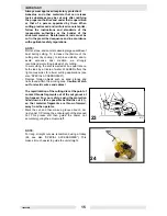
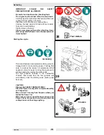
Turn the hood lock (2) to position

and hold it there.

Pivot the hood (3) back as far as it will go.
Release the hood lock and pivot the hood lightly back
and forth until the lock engages.

Cold-starting

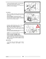
Move the combination switch (5) up (choke position).
Grasp handle (hand pressure actuates the grip throttle
lever lock (7)).
Push the throttle (8) in all the way and hold it.
Press the throttle lock (6) and release the throttle (8)
(the throttle lock will hold the throttle at half-throttle
position). Push the starting valve (4).

Grasp the tubular handle firmly with one hand and
press the Power Cut against the ground:
Place the tip of your left foot in the rear handle.
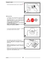
Slowly pull out the starter cable until you notice
resistance (the piston is positioned before the top
dead centre).
Now pull the starter cable with a fast and forceful
movement until you hear the first ignition.

Caution: Do not pull out the starter cable more than
approx. 50 cm, and lead it back by hand.
Press in the starting valve (42/4) in again.
Put the combination switch (42/5) in position “I“.
Keep pulling the starter cable until the engine catches.
As soon as the engine is running, press the throttle
(42/8) to release the half-throttle lock (42/6), allowing
the engine to idle.

Warm-starting

As described under „Cold starting“, except without
putting the combination switch (42/5) in choke
position.

41

42

43

Summary of Contents for BTS 1030

Page 1: ...www wackergroup com Operator s Manual POWER CUT BTS 930 BTS 935 BTS 1030 BTS 1035 FBTS 0200367en 10 2002 0008340 103 0008341 103 0008339 102 0007975 102 0125766...

Page 2: ......

Page 3: ...hts especially the right for copying and distribution are reserved Copyright by Wacker Construction Equipment AG No part of this publication may be reproduced in any form or by any means electronic or...

Page 4: ...21 PUTTING INTO OPERATION 22 Mounting the cutting disc 22 Tightening the V belt Checking V belt tension 23 Fuels 24 Refuelling 26 Starting the engine 26 Cold starting 28 Warm starting 28 Stopping the...

Page 5: ...SPECIAL ACCESSORIES 45 Instructions for periodic maintenance 46 Service spare parts and guarantee 47 Troubleshooting 48 LABELS 49 FBTS 51 Guide trolley 51 Safety precautions 51 CUTTING DISCS 52 CUTTIN...

Page 6: ...e unit man ually or on the side for flush cuts along walls or curbsides or horizontally directly above the ground Extensive range of accessories available such as resinoid bonded or diamond tipped cut...

Page 7: ...ls You will notice the following symbols on the saw and in the Instruction Manual Read instruction manual and follow the warning and safety precautions Combination Start Stop I O switch choke Particul...

Page 8: ...T00823GB 6 Direction of cutting wheel rotation First aid Warning the max peripheral speed of the cutting disc is 80 m s Recycling Cutting disc dimensions CE Marking...

Page 9: ...to accept liability for others Never work while under the influence of alcohol drugs medication or other substances which may impair vision dexterity or judgement Ar fire extinguisher must be availab...

Page 10: ...erial Fuels Refuelling Go to a safe level place before refuelling Never refuel while on scaffolding on heaps of material or in similar places Switch off the engine before refuelling the Power Cut Do n...

Page 11: ...the cutting disc direction of sparks Fuel cannot be stored for an unlimited period of time Buy only as much as will be consumed in the near future When making up the gasoline oil mixture always put th...

Page 12: ...d condition replace immediately if torn damaged or bent the cutting wheel is properly mounted the protective hood is locked in place the hand guard is properly mounted the V belt has the proper tensio...

Page 13: ...t the Power Cut into operation only as described in this instruction manual 13 Always place your left foot in the rear handle and grasp the other handle firmly with thumb and fingers Other starting me...

Page 14: ...ower Cut to be thrown back toward the user with great force and out of control Risk of injury To prevent kickback observe the following Never cut with the section of the cutting disc shown in figure 1...

Page 15: ...Cut in such a way that no part of your body is within the extended swing range of the disc 18 Use cutting discs only for the materials for which they are designed Use cutting discs only for the mater...

Page 16: ...smaller diameter than new discs so that at the same engine speed they have a lower effective circumferential speed and therefore do not cut as well Cut I beams and L bars in steps see Figure 21 Cut b...

Page 17: ...utting instead of dry cutting In wet cutting the disc is wetted at an equal rate on both sides by a trickle of water WACKER offers the right accessories for all wet cutting applications see also SPECI...

Page 18: ...e cutting disc before transporting the unit in a vehicle The Power Cut should be stored safely in a dry place It must not be left outdoors Always dismount the cutting disc before storage Keep the Powe...

Page 19: ...idents or damage occurring in association with the use of cutting discs or accessories other than original WACKER First aid For the event of a possible accident please make sure that a first aid kit i...

Page 20: ...T00823GB 18...

Page 21: ...Max spindle speed 1 min 4 300 Sound pressure level LpA eq per EN 1454 1 4 dB A 97 Vibration acceleration ah w per EN 1454 Tubular handle idle rated spindle speed Rear handle idle rated spindle speed...

Page 22: ...350 Max spindle speed 1 min 4 300 Sound pressure level LpA eq per EN 1454 1 4 dB A 99 Vibration acceleration ah w per EN 1454 Tubular handle idle rated spindle speed Rear handle idle rated spindle spe...

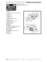
Page 23: ...od lock 8 V belt tension adjusting screw 9 Retaining nuts 10 Base 11 Carburetor adjustment opening 12 Identification plate 13 Fuel tank with handle 14 Starting valve 15 Starter grip 16 Air intake 17 C...

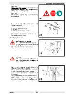
Page 24: ...he cutting disc Inspect the disc for damage See SAFETY INSTRUCTIONS Page 6 Unscrew screw 9 and remove the spring washer 8 Place the cutting disc 5 on the arbour 7 CAUTION When using a diamond cutting...

Page 25: ...bearing Retighten new V belt after first running hour NOTE The two fastening nuts 11 must be loosened before tightening the V belt or checking the tension To increase the belt tension turn the tighte...

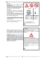
Page 26: ...Power Cut tank CAUTION Open the tank cap carefully as pressure might have built up inside It is not wise to add more engine oil than specified to ensure safe operation This will only result in a high...

Page 27: ...T00823GB 25...

Page 28: ...model features a semiautomatic starting valve 1 Happy Start to make starting easier Pushing this valve in reduces the amount of compression effort needed so that it is easier to bring the engine up t...

Page 29: ...T00823GB 27...

Page 30: ...e Power Cut against the ground Place the tip of your left foot in the rear handle Slowly pull out the starter cable until you notice resistance the piston is positioned before the top dead centre Now...

Page 31: ...ilure to follow these instructions can lead to damage to the cylinder and piston Turn the cover lock 2 to the unlocked position and carefully remove the filter cover 3 Take the filter element 4 out of...

Page 32: ...T00823GB 30...

Page 33: ...g speed to maximum speed must be tested by abruptly operating the throttle lever If the acceleration is too slow the idling speed jet screw 10 must be loosened slightly max 1 8 of a revolution and the...

Page 34: ...T00823GB 32...

Page 35: ...eel breaks during cutting the Power Cut must be repaired by a WACKER service station before being used again Changing the V belt Loosen nuts 3 Loosen the tightening screw 1 counter clockwise until the...

Page 36: ...T00823GB 34...

Page 37: ...with a cloth Cleaning changing the air filter Turn the cover lock 11 to the Unlocked position and carefully remove the filter cover 12 There is an O ring 57 15 between the filter cover 12 and the air...

Page 38: ...T00823GB 36...

Page 39: ...tle and tap it out on a clean surface Replace the cartridge periodically and especially in case of poor performance reduced engine speed or smoky exhaust Before reassembling the filter system check th...

Page 40: ...T00823GB 38...

Page 41: ...7A Replacing the suction head The felt filter 13 of the suction head can become clogged It is recommended to replace the suction head once every three months in order to ensure unimpeded fuel flow to...

Page 42: ...T00823GB 40...

Page 43: ...fan housing it may be necessary to pull the starter cable lightly so that the cable pulley catches Replacing the return spring Remove the fan housing see above under Replacing the starter cable Takeof...

Page 44: ...T00823GB 42...

Page 45: ...nt Loosen nuts 5 Loosen the tightening screw 3 counter clockwise until the end of the screw 4 is visible in the gap Unscrew the nuts 5 and remove the cover 6 Turn the hood lock 8 clockwise as shown in...

Page 46: ...t see Tightening the V belt Checking V belt tension Tighten the nuts 14 firmly with the combination wrench IMPORTANT When you reposition the cutting attachment the direction of rotation of the cutting...

Page 47: ...tent cutting performance and thus high economy The outstanding cutting qualities of the discs make cutting easier The metal disc plates give highly concentric running for minimal vibration during use...

Page 48: ...regularly for damage and wear Protection hood Clean Before each start Cutting disc Inspect for damage and make sure the cutting wheel is right for the job V belt Check V belt tension Combination switc...

Page 49: ...the latest improve ments and spare part innovations Please bear in mind that if parts other than original WACKER spare parts are used this will automatically in validate the WACKER product guarantee G...

Page 50: ...Cylinder base packing ring defective radial shaft packings defective cylinder or piston rings defective Outside Spark plug does not seal Mechanical malfunction Starter does not engage Spring in starte...

Page 51: ...SK00607GB 49 LABELS 1...

Page 52: ...SK00607GB 50 Ref Part No Qty Part 1 0125647 1 Decal Sound power level...

Page 53: ...es have been added to the area of the clamp lever thus making it easier to adjust the cutting depth of the blade One notch is equivalent to 10 mm cutting depth Safety precautions The mounting brackets...

Page 54: ...lightly reinforced D 6 mm o Concrete blocks curbstones Concrete cast stones o o o Pumice stones Floor topping finish or industrial floors o Fresh reinforced concrete D 6 mm w all types of aggregates...

Page 55: ...rete with very hard aggregates such as granite quarz or flint o Concrete Concrete blocks Pumice stones o Roof tiles o o Floor topping finish Wall plaster o o Floor tiles wall tiles ceramics o Granite...

Page 56: ...8236 Profi Universal Free hand 20 0 0108239 Profi Universal Free hand 22 2 0108240 High Speed Concrete 20 0 0126081 High Speed Asphalt 20 0 0126078 High Speed Granite 20 0 0126084 Version Application...

Page 57: ...talled power has been evaluated in conformity with Directive 2000 14 EC and has been manufactured in accordance with the following directives 2000 14 EG EMV Richtlinie 89 336 EG 98 37 EG Dr Sick Board...

Page 58: ...56...

Page 59: ......

Page 60: ......

Page 61: ......

Page 62: ......

Reviews: