background image

8 Operation and use

100_0202_op_0011.fm

31

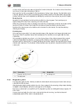
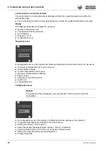
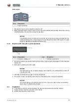
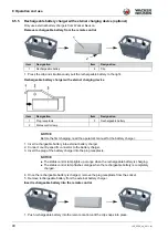
When the machine is activated, all control lamps light up for approx. 1 second.

The following are displayed in sequence:

Auto-engaging status.

The transmission channel set on the machine (optional).

Number of operating hours.

4. Close and lock rear protective hood into place.

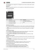
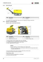
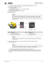
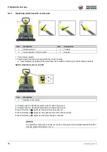
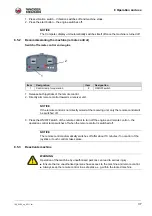
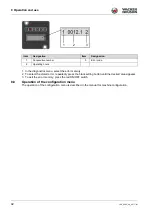
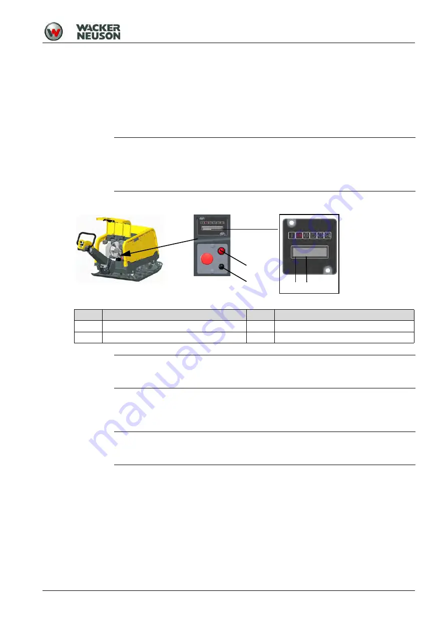
Enter activation PIN

1. When the display prompts you to enter the activation PIN, press the ON/OFF switch.
2. Enter activation PIN:

To select the next position, press the ON/OFF switch on the machine.

To select the digit, press the selection button repeatedly until the correct value is achieved.

3. Once all of the digits of the activation PIN have been selected, press the ON/OFF switch of the 

machine.

NOTICE

PIN entry is deactivated by default. If the machine should be secured by an activation PIN, 
this must be set in the configuration menu; see 

Manual for Machine Configuration.

The activation PIN should always be kept secret and never be listed on the machine or 
remote control.

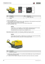
Item

Designation

Item

Designation

1

Digit of the activation PIN

3

ON/OFF switch (red)

2

Position of the activation PIN

4

Adjusting key (black)

NOTICE

The engine can only be started if the correct activation PIN has been entered with the 
remote control.

NOTICE

If an incorrect PIN is entered four times in succession, you must wait five minutes before 
re-entering the PIN. During the wait time, the request to wait is displayed.

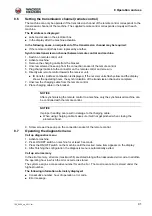
1 2

3

4

0XXX

Summary of Contents for DPU80 Series

Page 1: ...Operator s manual Vibratory plate DPU 80 90 110 Model DPU Document 5100008833 Issue 06 2016 Version 06 Language en ...

Page 2: ...he statutory provisions in particular the protection of copyright will lead to civil and criminal prosecution Wacker Neuson Produktion GmbH Co KGis constantly working on the improvement of its products as part of the technical further development Therefore we reserve the right to make changes to the illustrations and descriptions in this documentation without incurring any obligation to make chang...

Page 3: ...bricants and coolants 11 3 11 General safety instructions starter batteries 11 3 12 Maintenance 11 3 13 Personal Protective Equipment 12 3 14 Safety devices 12 3 15 Behavior in dangerous situations 13 4 Safety and information labels 14 4 1 Safety and information labels on the remote control 15 5 Setup and function 16 5 1 Standard package 16 5 2 Application areas 16 5 3 Short description 16 5 4 Ver...

Page 4: ...10 4 Troubleshooting chart remote control 54 10 5 Troubleshooting table display 55 10 6 Perform jump start with donor starter battery 59 11 Disposal 61 11 1 Disposal of batteries 61 12 Accessories 62 13 Technical data 63 13 1 DPU80 63 13 2 DPU80r 64 13 3 DPU90 65 13 4 DPU90r 66 13 5 DPU110 67 13 6 DPU110r 68 13 7 Combustion engine 69 13 8 US combustion engine 70 14 Emission control systems informa...

Page 5: ...al is not a manual for extensive maintenance or repair work Such work should be carried out by Wacker Neuson service or by technically trained personnel The Wacker Neuson machine should be operated and maintained in accordance with this operator s manual An improper operation or improper maintenance can pose dangers Therefore the operator s manual should be constantly available at the location of ...

Page 6: ... change this information The manufacturer shall immediately include any modifications or additions in this manual 2 5 Target group Individuals working with this machine must be regularly trained on the dangers of handling the machine This operator s manual is intended for the following persons Operating personnel These individuals have been trained on the machine and informed about the possible da...

Page 7: ... to follow this manual Unintended use Deployment of untrained personnel Using non approved spare parts and accessories Improper handling Structural modifications of any kind Failure to observe the General Terms and Conditions GT Cs 2 9 Product identification of the machine Data of the nameplate The nameplate contains information that uniquely identifies this machine This information is required fo...

Page 8: ... in risks to the operator and or third parties as well as damage to the machine In the case of unauthorized structural changes the liability and warranty of the manufacturer are no longer applicable The following cases are considered structural changes Opening the machine and the permanent removal of components Installing spare parts that do not originate from Wacker Neuson or are not comparable i...

Page 9: ... standards of safety engineering 3 5 General sources of danger Residual dangers in particular are hazards when dealing with machines that despite a safe design cannot be eliminated These residual dangers are not obvious and may be the source of a possible injury or health hazard If unforeseeable residual dangers occur the operation of the machine is to be stopped immediately and the competent supe...

Page 10: ...ne leaks from bottom Explosion hazard In dry flammable vegetation Fire hazard In potentially explosive areas Explosion hazard 3 7 2 Operational safety When operating the machine make sure that no gas water or electric lines are damaged The machine must not be operated in tunnels or enclosed spaces Pay maximum attention near drops or slopes Risk of crashing The operator must not leave the machine w...

Page 11: ...l oil or coolant gets into your eyes consult a physician immediately Avoid direct skin contact with fuel lubricants and coolants Immediately rinse skin with soap and water Do not eat or drink while working with fuel lubricants and coolants Hydraulic oil or fuel contaminated by dirt or water can cause premature wear or failure of the machine Dispose of spilled fuel lubricants and coolants according...

Page 12: ...al measures This prevents the user from being exposed to a danger The source of danger will be eliminated in certain situations or the danger will be reduced NOTICE To prevent personal injury when handling this machine personal protective equipment must be worn when working on or around this machine Pictogram Significance Description Wear safety shoes Safety shoes provide protection from bruises f...

Page 13: ...a approx 1 2 meters from a receiving unit When the operator leaves the receiving area a maximum of 20 meters from the machine Interruption of the clear line of sight between the remote control and receiving units of the machine Power failure of remote control and or machine 3 15 Behavior in dangerous situations Preventive measures Always be prepared for accidents Keep first aid equipment on hand M...

Page 14: ...njury Only lift machine at the central lifting point with certified lifting gear and tackle safety load hook Do not lift the machine on the central lifting point with an excavator bucket Do not lift the machine on the central lifting point with a forklift 3 Guaranteed sound power level 4 Center pole machines Falling machines can cause serious injury Do not lift the machine with the control handle ...

Page 15: ...9 Warning against hot surface 10 Tie down lugs Item Label Description 1 US Machines To prevent interference of the infrared transmission and possible machine malfunction do not attach to housing Clean before transmitter and receiver eye before commissioning Clean remote control and receiving unit before commissioning 2 US Machines To prevent damage and possible malfunction of the transmitter unit ...

Page 16: ... the front To start the drive motor automatically the glow plugs are preheated The speed of the drive motor is controlled via a lifting magnet The machine is switched off via an electrically controlled solenoid valve on the fuel filter The electrical control unit is located in the electrical box The operator s controls are located at the electrical box and at the center pole head The maintenance f...

Page 17: ...or it will cease all vibration and movement Once the operator leaves the proximity area the machine is once again able to receive commands If the operator is laterally closer than 1 2 m from the machine or if the infrared signals of the remote control are transmitted via reflection a stopping of the vibration and movement is not guaranteed If another person comes within 1 2 meters proximity area o...

Page 18: ...ory Switch over to slow mode 5 3 5 Compatec system optional The Compatec system is integrated into the rear protective hood and is located within the operator s line of sight The display which consists of eight light adjusting LEDs displays the relative compaction progress while driving by successively lighting up When the number of illuminated LEDs no longer increases this means that no further c...

Page 19: ...the current operating status of the machine To better distinguish between the front and rear of the machine the receiving units have different colors Eyelet for padlock The rear protective hood features a lug for attaching a padlock The machine is thus protected against unauthorized opening of the rear protective hood as well as unauthorized operation Bracket for remote control and charging cable ...

Page 20: ...ocking the emergency stop switch Height adjustment mechanism of center pole The center pole height adjustment mechanism allows for continuous height adjustment in order to adjust the center pole individually to the optimum working height This is done by turning the star knob In addition by pushing down on the star knob the center pole can be brought into the lower position e g to be able to travel...

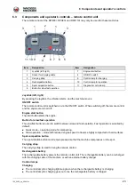
Page 21: ...starter battery of the machine is no longer charged Control lamp for preheating When the engine is started the control lamp for preheating indicates whether the glow plugs are being preheated The control lamp for preheating lights up yellow as long as the glow plugs of the engine are preheated during starting The control lamp for preheating goes out when preheating is completed Control lamp for ai...

Page 22: ...about the machine can be accessed Overview of all detected errors error memory Starter battery voltage Coolant temperature of the engine Hydraulic oil temperature optional Engine speed Software version SW version Switch test Transmission test Configuration menu In the configuration menu on the display the following machine settings can be adjusted Change activate deactivate activation PIN of the m...

Page 23: ... highly compacted or hard surfaces Spot compaction button The spot vibration button must remain pressed so that the machine compresses on the spot Carrying strap The carrying strap is used to hang the remote control Rechargeable battery The rechargeable battery powers the remote control unit The rechargeable battery can be recharged with the charging cable of the machine or with an external batter...

Page 24: ...shes green when the remote control is switched on The control lamp for operation flashes red when the charge situation of the rechargeable battery is low The control lamp for operation lights up red when the rechargeable battery is discharged Diagnostics The control lamp for diagnosis briefly flashes green when a joystick is moved or a button on the remote control unit is pressed ...

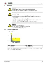
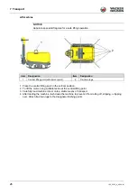
Page 25: ...us injury e g through crushing Only use suitable and tested lifting gear and tackle safety load hooks of sufficient lifting capacity Only lift the machine from the central lifting point Reliably secure the machine to the lifting gear Do not lift the machine on the central lifting point with a forklift or excavator bucket Do not lift the machine at the control handle Evacuate danger zone while lift...

Page 26: ...arefully load machine into or onto a stable means of transport 4 After loading the machine lash down the machine to prevent it from rolling off slipping or tipping over Attach tie down lugs to the designated lashing points NOTICE Appoint a specialist flagman for a safe lifting operation Item Designation Item Designation 1 Central lifting point attachment point 2 Tie down lugs 1 2 ...

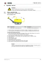
Page 27: ...as been removed from the machine Ensure that there are no loose items under the protective hoods e g gloves or tools Check fuel level Check the engine oil level Check hydraulic oil level Check the fuel lines for leak tightness Check to ensure the screwed connections are firmly seated Ensure that the receiving units are free of dirt accumulation WARNING Improper handling may result in injury or ser...

Page 28: ...rging cable in the bracket 5 Screw screwed nose cap on the connection socket of the remote control 6 Remove the remote control from the bracket Check remote control Remote control and carrying strap are undamaged Remote control is free of dirt Item Designation Item Designation 1 Center pole 2 Star knob Item Designation Item Designation 1 Remote control 3 Charge cable 2 Bracket for remote control 4...

Page 29: ...n WARNING Danger of tipping There is a serious risk of injury from slipping or tipping over of the machine Near edges at least 2 3 of the machine must be on a load bearing surface If not decommission the machine and lift back on a load bearing surface WARNING Health hazard from exhaust fumes The exhaust fumes of this engine contain chemicals which the state of California knows can cause cancer bir...

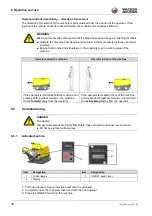
Page 30: ...danger of crushing for others Operate the machine from behind and maintain a minimum safety distance of at least 2 meters Ensure that no other individuals are in the proximity area or working area of the machine Operator behind the machine Operator in front of the machine If the operator is located behind the machine and presses both joysticks forward the machine moves forward away from the operat...

Page 31: ...ll of the digits of the activation PIN have been selected press the ON OFF switch of the machine NOTICE PIN entry is deactivated by default If the machine should be secured by an activation PIN this must be set in the configuration menu see Manual for Machine Configuration The activation PIN should always be kept secret and never be listed on the machine or remote control Item Designation Item Des...

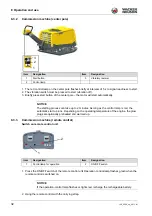
Page 32: ...e remote control unit Operation control lamp flashes green when the remote control is switched on 2 Hang the remote control with the carrying strap Item Designation Item Designation 1 Start button 3 Vibratory rammer 2 Control lamp NOTICE The starting process can take up to 2 minutes As long as the control lamp is red the automatic start up runs Depending on the operating temperature of the engine ...

Page 33: ... for operation 8 4 Operation In accordance with the intended purpose the operator should stand behind the machine Guide and steer machine using the control handle Control machine with remote control Item Designation 1 Engine start button NOTICE The starting process can take up to 2 minutes As long as the receiving units light red the automatic startup will run Depending on the operating temperatur...

Page 34: ...crease the speed Slowly press the slow fast switch down to reduce the speed If the control lamp lights up the maximum speed is set If the control lamp lights up the speed is lower than the maximum If the control lamp lights up the lowest stage is reached Item Designation Item Designation 1 Vibratory rammer 3 Forward 2 Central position of control handle 4 Reverse Item Designation 1 Slow fast rocker...

Page 35: ...ine is in slow mode Switching stand vibration on and off 1 Pressing and holding stand vibration button The machine compresses on the spot without moving in one direction 2 Releasing stand vibration button The machine will return to normal operating condition 8 4 3 Machine protection installation optional To protect the machine a warning is activated in the event of an overload The red control lamp...

Page 36: ...king area NOTICE It is possible to detect non compactable material if the spot is longer than one meter In the case of abrupt change from high to low compacted soil or vice versa there is a slow increase or decrease of the LEDs NOTICE The LED bar utilization of the Compatec display unit is tailored to soils that can be compacted easily A soil density that is well beyond the achievable values of so...

Page 37: ...ed off 8 5 3 Deactivate machine NOTICE The Compatec display unit automatically switches itself off once the machine is turned off Item Designation Item Designation 1 Control lamp for operation 2 ON OFF switch NOTICE If the remote control is not directly aimed at the receiving unit only the remote control will be switched off NOTICE The remote control automatically switches off after about 10 minut...

Page 38: ...top moving and vibrating and will automatically deactivate itself To unlock turn the emergency stop switch to the left The machine can then be re activated Item Designation Item Designation 1 Control lamps 3 ON OFF switch red 2 Display NOTICE If the machine is not deactivated it will automatically deactivate after about 15 minutes center pole machine or after about 1 hour remote controlled machine...

Page 39: ...rging the battery is not possible the charging cable must not be disconnected from the remote control after charging Note that after a longer downtime service life of the machine the rechargeable battery charges more slowly It may need to be recharged A charging time of 15 min is sufficient to operate the machine for about 1 h Item Designation Item Designation 1 Remote control 4 Bracket for charge...

Page 40: ... plug receptacle 4 Once the rechargeable battery is charged remove the plug receptacle from the socket 5 Remove rechargeable battery from the external battery charger Insert rechargeable battery into the remote control 1 Push rechargeable battery into the remote control until the clip snaps into place Item Designation Item Designation 1 Rechargeable battery 2 Clip Item Designation Item Designation...

Page 41: ...g hours the synchronization of the transmission channel is complete 7 Unscrew the charging cable from the remote control 8 Place charging cable in the bracket 9 Screw screwed nose cap on the connection socket of the remote control 8 7 Operating the diagnostic menu Call up diagnostics menu 1 Activate machine 2 Press ON OFF switch on machine for at least 3 seconds 3 Press the ON OFF switch on the ma...

Page 42: ...ss the black setting button until the desired area appears 3 To exit the error memory press the red ON OFF switch 8 8 Operation of the configuration menu The operation of the configuration menu is described in the manual for machine configuration Item Designation Item Designation 1 Consecutive number 3 Error code 2 Operating hours 1 2 3 ...

Page 43: ...ce jobs with the engine switched off and the machine decommissioned WARNING Risk of fire and explosion from fuel and fuel vapors Fuel and fuel vapors may ignite or catch fire and cause serious burns Do not smoke Do not refuel near open flames Switch off the engine and allow to cool before refueling WARNING Warning of hot surfaces The exhaust system and engine can become extremely hot which can lea...

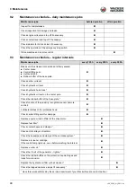
Page 44: ...ic oil level Check hydraulic hose lines Check hydraulic oil level on the center pole Check the rubber buffer of the base plate Check function of the proximity recognition sensor remote control Lubricate latches of the protective hood Check central lifting point for damage Replace engine oil and oil filter of the drive motor Replace fuel filter Check coolant hoses and clamps Check anti frost layer ...

Page 45: ...e the hydraulic oil Replace the tooth belt pulley of the engine Replace the hydraulic hose lines Have this work performed by the service department of your Wacker Neuson contact partner CAUTION Health risk from fuel lubricants and coolants Do not inhale fuel lubricants coolants or vapors Avoid contact of skin or eyes with fuel lubricants and coolants WARNING Risk of fire and explosion from fuel an...

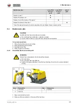
Page 46: ... dipstick with a dry lint free cloth 5 Fully reinsert oil level dipstick 6 Pull out oil level dipstick 7 Check whether the oil is between the lower and upper mark of the oil level dipstick Top off motor oil 1 Remove dirt accumulation in the area of the oil filler opening 2 Remove cover of the oil filler opening NOTICE Dispose of impurities of the fuel filter in accordance with the applicable provi...

Page 47: ...drained screw in the oil drain plug and tighten 8 Screw in a new oil filter and tighten with 20 Nm Fill motor oil 1 Remove dirt accumulation in the area of the oil filler opening 2 Remove cover of the oil filler opening 3 If necessary fill with oil until the upper mark of the oil level dipstick is reached for oil specification and amount of oil see Technical Data chapter 4 Put the cover back on th...

Page 48: ...irty If necessary squeeze dust discharge valve to remove the dirt Replace air cleaner cartridge 2 Loosen clamps and remove lower housing part 3 Remove air cleaner cartridge 4 Clean lower housing part 5 Insert air cleaner cartridge 6 Replace lower housing part and seal clamps Item Designation Item Designation 1 Air cleaner 2 Dust discharge valve Item Designation Item Designation 1 Air cleaner cartr...

Page 49: ...tor 1 Remove dirt accumulation in the area of the radiator cover 2 Slowly unscrew the radiator cap and remove 3 Check whether the coolant reaches the upper edge of the filler opening Top off coolant in the radiator 1 If necessary top off the coolant to the upper edge of the filler opening for the coolant specification see the Technical Data chapter 2 Replace radiator cap and tighten Item Designati...

Page 50: ...off the exciter oil with a clean funnel at the oil filler drain opening until the exciter oil reaches the lower thread for the oil specification see the Technical Data chapter 2 Screw in the screw plug of the oil filler drain opening along with a new seal ring and tighten torque setting of 100 Nm 3 Wipe away any spilled oil Item Designation Item Designation 1 Screw plug with seal ring of the oil f...

Page 51: ...n see Technical Data chapter 6 Replace cover of the hydraulic tank and tighten torque setting of 10 Nm make sure that the seal of the cover fits properly 9 4 9 Screwed connections For the vibratory plates the screwed connections must be regularly checked for a firm seat Item Designation Item Designation 1 Cover of the hydraulic oil tank 2 Oil level glass NOTICE If the machine is losing hydraulic o...

Page 52: ...lace fuel filter Air cleaner is dirty Clean or replace air cleaner Vibration will not start Electrical system defective Have the machine repaired Engine smokes and does not perform Air cleaner is dirty Replace air cleaner Machine cannot be activated Incorrect activation PIN entered Enter the correct activation PIN Deactivate machine with emergency stop switch Electrical system defective 1 Deactiva...

Page 53: ...d to commands from the remote control Operator is located in the proximity area Leave the proximity area of the machine Receiver units light up red Machine is in the warm up phase Wait until the warm up phase has completed Diagnostic system has detected an error Check control lamps and fault indications on the display Receiver units flash red Machine is overloaded because the soil cannot be compac...

Page 54: ...able battery After switching on the remote control the operation control lamp does not flash Rechargeable battery of the remote control is discharged Load or replace rechargeable battery of the remote control Remote control is defective Have remote control replaced or repaired Charging control lamp flashes green The rechargeable battery is automatically being pre warmed for charging Charging the b...

Page 55: ...d Warm up control lamp lights up yellow Machine is in the startup process Wait until the engine starts Air cleaner control lamp lights up yellow Air cleaner cartridge is dirty Replace air cleaner cartridge Oil pressure control lamp lights up when the engine is running Engine oil level is too low Top up motor oil Oil pressure switch or electrical connection is defective Have the machine repaired Co...

Page 56: ...Battery error Alternator charge controller battery or electrical connection is defective 7 Check air cleaner Air cleaner cartridge is dirty Replace air cleaner cartridge Electrical connection of the air cleaner sensor is defective Have the electrical connection of the air cleaner sensor checked 8 Air cleaner error Air cleaner sensor is defective Have the machine repaired Electrical connection of t...

Page 57: ...ow Top up coolant Engine is overheated Allow engine to cool down Cooling fins of the cooler are dirty Blow cooling fins with compressed air from the inside to the outside from a safe distance Cooling system is leaking Have the machine repaired Temperature sensor or electrical connection is defective 19 Excess temperature of the machine Coolant level is too low Top up coolant Engine is overheated A...

Page 58: ... oil Oil pressure switch or electrical connection is defective Have the machine repaired 27 Overload sensor error Overload sensor or electrical connection is defective 28 Overload sensor error Defective overload sensor 29 IR receiver error Incorrect current value 30 IR receiver error No power not connected 31 Shutdown of the center pole unit No signal not connected 32 Shutdown error of the decoder...

Page 59: ...ck Perform jump start 5 Start engine If the engine does not start after a maximum of two minutes contact your Wacker Neuson contact person 6 Run engine for a few minutes WARNING Risk of explosion from explosive gas Risk of injury from splashing acid Wear safety glasses and protective gloves The donor battery and starter battery of the machine must have the same voltage 12 V Avoid short circuit fro...

Page 60: ...ing point of the machine 8 Disconnect second clamping tongs of the black jumper cable from the donor starter battery 9 Disconnect clamping tongs of the red jumper cable from the positive terminal of the discharged starter battery 10 Disconnect clamping tongs of the red jumper cable from the positive terminal of the discharged donor battery ...

Page 61: ...es may not be disposed of with normal household waste As an end user you may only dispose of used batteries via the manufacturer or specially equipped collection facilities statutory obligation to return the delivery is free Retailers and manufacturers are obliged to take back these batteries and properly recycle them or dispose of them as hazardous waste legal obligation Batteries obtained throug...

Page 62: ... without interruption External battery charger The external battery charger charges the rechargeable battery when it cannot be charged via the charging cable of the machine The external battery charger has a country specific plug to connection to various current networks CAUTION Accessories and spare parts that do not originate from Wacker Neuson can increase the risk of injury and possible damage...

Page 63: ...raulics bar 165 165 Maximum allowable hydraulic pressure bar 230 230 Coolant volume l 3 8 3 8 Type of coolant SAE J1034 water 1 1 SAE J1034 water 1 1 Exciter oil volume l 1 35 1 35 Exciter oil type M 75W90 M 75W90 Hydraulic oil volume l 17 7 17 7 Type of hydraulic oil MR 520 MR 520 Storage temperature range C 20 50 20 50 Operating temperature range C 10 50 10 50 Sound pressure level At location of...

Page 64: ...h 8 8 Recommended battery type Ni MH 7 2 V 2000 mAh Ni MH 7 2 V 2000 mAh Battery charging time h 2 2 Working pressure of hydraulics bar 165 165 Maximum allowable hydraulic pressure bar 230 230 Coolant volume l 3 8 3 8 Type of coolant SAE J1034 water 1 1 SAE J1034 water 1 1 Exciter oil volume l 1 6 1 6 Exciter oil type M 75W90 M 75W90 Hydraulic oil volume l 17 7 17 7 Type of hydraulic oil MR 520 MR...

Page 65: ...148 148 Maximum allowable hydraulic pressure bar 230 230 230 Coolant volume l 3 8 3 8 3 8 Type of coolant SAE J1034 water 1 1 SAE J1034 water 1 1 SAE J1034 water 1 1 Exciter oil volume l 1 35 1 35 1 35 Exciter oil type M 75W90 M 75W90 M 75W90 Hydraulic oil volume l 17 7 17 7 17 7 Type of hydraulic oil MR 520 MR 520 MR 520 Storage temperature range C 20 50 20 50 20 50 Operating temperature range C ...

Page 66: ...f remote control h 8 Recommended battery type Ni MH 7 2 V 2000 mAh Battery charging time h 2 Working pressure of hydraulics bar 148 Maximum allowable hydraulic pressure bar 230 Coolant volume l 3 8 Type of coolant SAE J1034 Wasser 1 1 Exciter oil volume l 1 6 Exciter oil type M 75W90 Hydraulic oil volume l 17 7 Type of hydraulic oil MR 520 Storage temperature range C 20 50 Operating temperature ra...

Page 67: ...93 193 193 Maximum allowable hydraulic pressure bar 230 230 230 Coolant volume l 4 2 4 2 4 2 Type of coolant SAE J1034 water 1 1 SAE J1034 water 1 1 SAE J1034 water 1 1 Exciter oil volume l 1 35 1 35 1 35 Exciter oil type M 75W90 M 75W90 M 75W90 Hydraulic oil volume l 21 9 21 9 21 9 Type of hydraulic oil MR 520 MR 520 MR 520 Storage temperature range C 20 50 20 50 20 50 Operating temperature range...

Page 68: ...ol h 8 8 Recommended battery type Ni MH 7 2 V 2000 mAh Ni MH 7 2 V 2000 mAh Battery charging time h 2 2 Working pressure of hydraulics bar 193 193 Maximum allowable hydraulic pressure bar 230 230 Coolant volume l 4 2 4 2 Type of coolant SAE J1034 water 1 1 SAE J1034 water 1 1 Exciter oil volume l 1 6 1 6 Exciter oil type M 75W90 M 75W90 Hydraulic oil volume l 21 9 21 9 Type of hydraulic oil MR 520...

Page 69: ...8 Max slanting position 25 25 25 Fuel type Diesel Diesel Diesel Fuel consumption l h 2 7 2 7 3 3 Tank capacity l 7 2 7 2 11 2 Oil specification SAE 10W40 SAE 10W40 SAE 10W40 Max oil filling l 1 6 1 6 2 4 Max performance kW 11 5 11 7 18 5 Speed 1 min 3 600 3 600 3 600 Standards ISO 3046 1 IFN Air cleaner Dry type air cleaner Dry type air cleaner Dry type air cleaner Starter type Electric starter El...

Page 70: ...placement cm 686 1 028 Max slanting position 25 25 Fuel type Diesel Diesel Fuel consumption l h 2 7 3 3 Tank capacity l 7 2 11 2 Oil specification SAE 10W40 SAE 10W40 Max oil filling l 1 6 2 4 Max performance kW 11 7 18 5 Speed 1 min 3 600 3 600 Standards ISO 3046 1 IFN ISO 3046 1 IFN Air cleaner Dry type air cleaner Dry type air cleaner Starter type Electric starter Electric starter Voltage of st...

Page 71: ...ol systems information and warranty The Emission Control Warranty and associated information is valid only for the U S A its territories and Canada Emission control systems warranty statement See the engine owner s manual for the applicable exhaust and evaporative emission warranty statement ...

Page 72: ...he relevant provisions and requirements of the following guidelines and standards 2006 42 EC 2009 10 2000 14 EC 2006 06 EN 500 1 2009 12 EN 500 4 2011 02 Person responsible for technical documents Robert Räthsel Wacker Neuson Produktion GmbH Co KG Preußenstraße 41 80809 München Product DPU80Le DPU90Le DPU110Le Product type Vibratory plate Function of product Soil compaction Item number 5100016604 ...

Page 73: ...complies with the relevant provisions and requirements of the following guidelines and standards 2006 42 EC 2009 10 2000 14 EC 2006 06 2014 30 EU 2014 02 EN 500 1 2009 12 EN 500 4 2011 02 EN 13309 2010 12 Person responsible for technical documents Robert Räthsel Wacker Neuson Produktion GmbH Co KG Preußenstraße 41 80809 München Product DPU80rLe DPU110rLe Product type Vibratory plate Function of pr...

Page 74: ......
Reviews: