OM ET18/20/24 us 1.3 * et18_20_24w700.fm
7-19
7
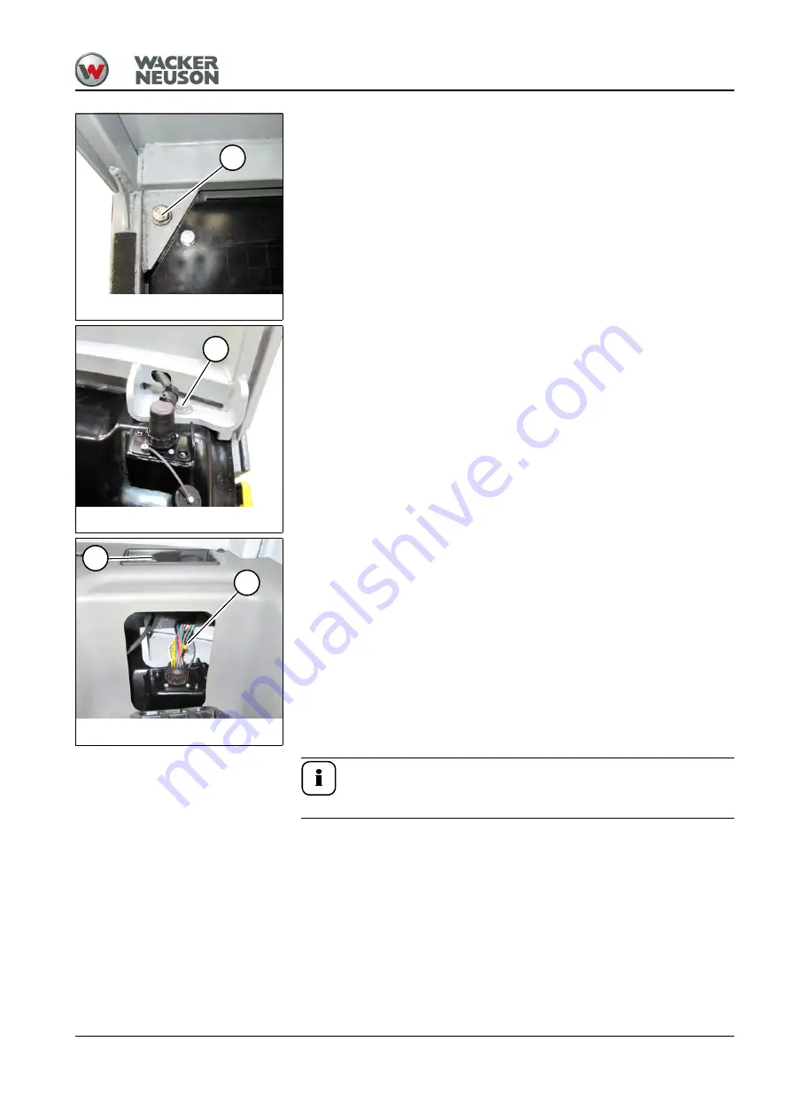
10.Raise the floor mat on either side.
11.Remove screws
D
on either side in the leg-room area.
12.
Canopy:
Remove screws
E
on either side.
13.
Cab (option):
Remove screws
E
on either side.
14.Raise the cab as follows:
- Raise the control lever base.
- Remove the starting key and carry it with you.
- Close the doors, windows and all covers.
- Remove all loose objects from inside the machine.
- Leave the cab.
- Close and lock all covers.
15.Set down the cab safely and ensure that it cannot tip over.
16.Install the cab in the reverse order.
17.Tighten screws
D
and
E
to 110 Nm (81 ft.lbs). The washers and
securing elements can be used again.
Information
Cover
F
can be removed for better access.
Fig. 237: Left and right-hand screws
D
Fig. 238: Screws (canopy)
E
Fig. 239: Screws (cab)
E
F
Summary of Contents for ET18
Page 12: ...1 6 OM ET18 20 24 us 1 3 et18_20_24v100 fm 1 Notes...
Page 39: ...OM ET18 20 24 us 1 3 et18_20_24e300 fm 3 11 3 Warning labels Fig 13 Warning labels Cab Canopy...
Page 44: ...3 16 OM ET18 20 24 us 1 3 et18_20_24e300 fm 3 Labels Fig 28 Labels...
Page 154: ...5 60 OM ET18 20 24 us 1 3 et18_20_24b510 fm 5 Notes...
Page 162: ...6 8 OM ET18 20 24 us 1 3 et18_20_24t600 fm 6...
Page 215: ...OM ET18 20 24 us 1 3 et18_20_24w710 fm 7 53 7 Notes...
Page 216: ...7 54 OM ET18 20 24 us 1 3 et18_20_24w710 fm 7...
Page 261: ...OM ET18 20 24 us 1 3 et18_20_24t900 fm 9 43 9 Cab canopy standard travel gear and VDS...
Page 262: ...9 44 OM ET18 20 24 us 1 3 et18_20_24t900 fm 9 Dimensions Overview ET18 ET20 ET24...
Page 266: ...9 48 OM ET18 20 24 us 1 3 et18_20_24t900 fm 9 Notes...


