1-6
BA E16 en* 1.0 * E16_10_100.fm
1 Foreword
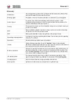
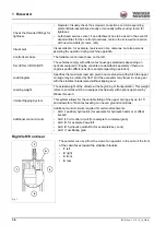
Right/left/front/rear
These terms are used from the view of an operator in the cabin if the front
of the cabin faces toward the stabilizer blade
A
.
•
1
: left
•
2
: right
•
3
: front
•
4
: rear
Check the threaded fittings for
tightness
• Operator: Visually check the screwed connections and corresponding
elements/sub-assemblies visually or manually (without using tools) for
tightness
• Authorized service center: if an attachment has to be used in the event of
abnormalities for the control procedures, restore the screwed connection
with new materials (screws, nuts)
Visual aids
Visual aids are, for example, rearview mirrors, cameras, but also persons
assisting the operator during machine operation.
Control lever base
The foldable control lever base on the left.
Tier III/Tier IV/DOC/DPF
The vehicles comply with different exhaust-gas standards depending on
optional equipment. Engine variants are described separately if there are
engine-specific differences (for example regarding operation).
Load diagram
Specifies the maximum load at a given boom extension with which the upper
carriage may be rotated by 360° and the excavator may travel in creep gear
with the stabilizer blade raised without tipping over.
Loading weight
The actual weight of the vehicle at the beginning of transportation. This weight
refers to vehicles which are equipped exclusively with options approved by
Wacker Neuson.
Vertical Digging System
This system allows for the variable tilting of the upper carriage by up to 15°
and allows for efficient excavating on uneven ground conditions.
Additional control circuits
Additional control circuits required for certain attachments.
• AUX I: auxiliary hydraulics (for example for hydraulic hammer or offset
bucket)
• AUX II: 3rd control circuit (for example for universal grab)
• AUX III: for example Powertilt
• AUX IV: hydraulic quickhitch (for example Easy Lock)
• AUX V: oscillating grab
Fig. 1
4
2
1
3
A
Summary of Contents for ET35
Page 14: ...1 8 BA E16 en 1 0 E16_10_100 fm 1 Foreword Notes...
Page 46: ...3 8 BA E16 en 1 0 E16_10_300 fm 3 Introduction Warning labels Fig 9 symbolic representation...
Page 64: ...3 26 BA E16 en 1 0 E16_10_300 fm 3 Introduction Notes...
Page 194: ...6 8 BA E16 en 1 0 E16_10_600 fm 6 Transportation Notes...
Page 252: ...8 8 BA E16 en 1 0 E16_10_800 fm 8 Malfunctions Notes...
Page 292: ...9 40 BA E16 en 1 0 E16_10_900 fm 9 Technical data 9 15 Dimensions ET35 symbolic representation...
Page 294: ...9 42 BA E16 en 1 0 E16_10_900 fm 9 Technical data EZ36 symbolic representation...
Page 296: ...9 44 BA E16 en 1 0 E16_10_900 fm 9 Technical data Notes...
Page 300: ...S 4 BA E16 en 1 0 E16_10_3SIX fm...


