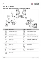
5-22
OM EZ17 us 1.0 * ez17b510.fm
5
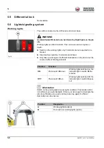
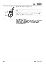
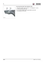
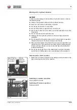
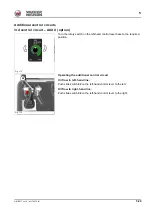
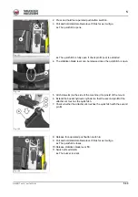
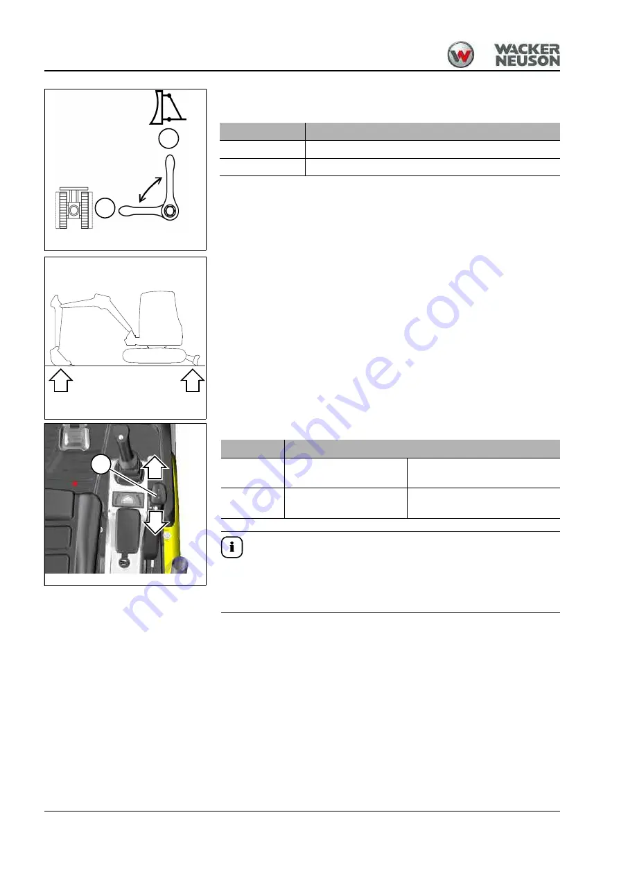
The lever is located at the left under the seat.
1. Set the lever to position
B
.
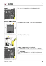
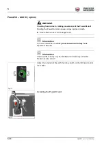
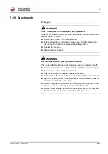
2. Raise the machine evenly and horizontally by means of the boom and
the stabilizer blade.
3. The telescopic travel gear is controlled via lever
10
.
Information
In order to ensure maximum stability during work:
►
Only perform work with an extended telescopic travel gear.
►
Lower the stabilizer blade and turn out the extensions.
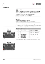
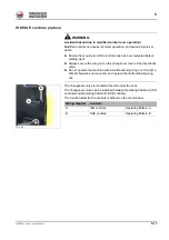
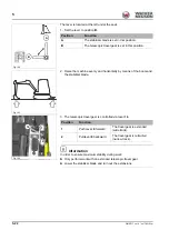
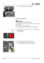
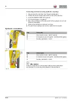
A
B
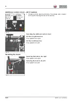
Fig. 102
Position
Function
A
The stabilizer blade is set in this position.
B
The telescopic travel gear is set in this position.
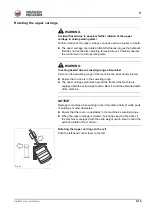
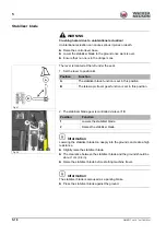
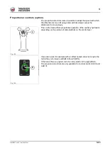
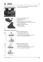
Fig. 103
1
2
10
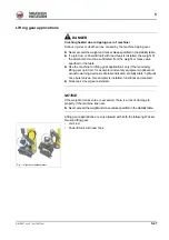
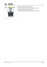
Fig. 104
Position
Function
1
Push lever
8
forward
The travel gear is extended
(wide track).
2
Pull lever
8
backward
The travel gear is retracted
(narrow track).
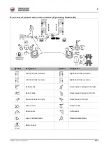
Summary of Contents for EZ17
Page 12: ...1 6 OM EZ17 us 1 0 ez17v100 fm 1 Notes...
Page 38: ...3 10 OM EZ17 us 1 0 ez17e300 fm 3 Warning labels Fig 11 symbolic representation...
Page 43: ...OM EZ17 us 1 0 ez17e300 fm 3 15 3 Labels Fig 24 symbolic representation...
Page 48: ...3 20 OM EZ17 us 1 0 ez17e300 fm 3 Notes...
Page 138: ...5 56 OM EZ17 us 1 0 ez17b510 fm 5 Notes...
Page 146: ...6 8 OM EZ17 us 1 0 ez17t600 fm 6...
Page 198: ...7 52 OM EZ17 us 1 0 ez17w710 fm 7 Notes...
Page 202: ...8 4 OM EZ17 us 1 0 ez17b800 fm 8 Notes...
Page 222: ...9 20 OM EZ17 us 1 0 ez17t900 fm 9 Dimensions Overview EZ17 Fig 227...


