


OM EZ17 us 1.0 * ez17b510.fm
5-29
5
Additional control circuits
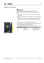
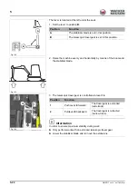
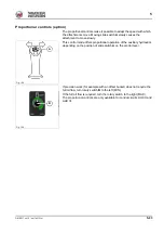
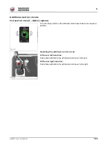
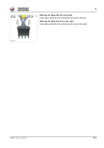
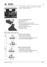
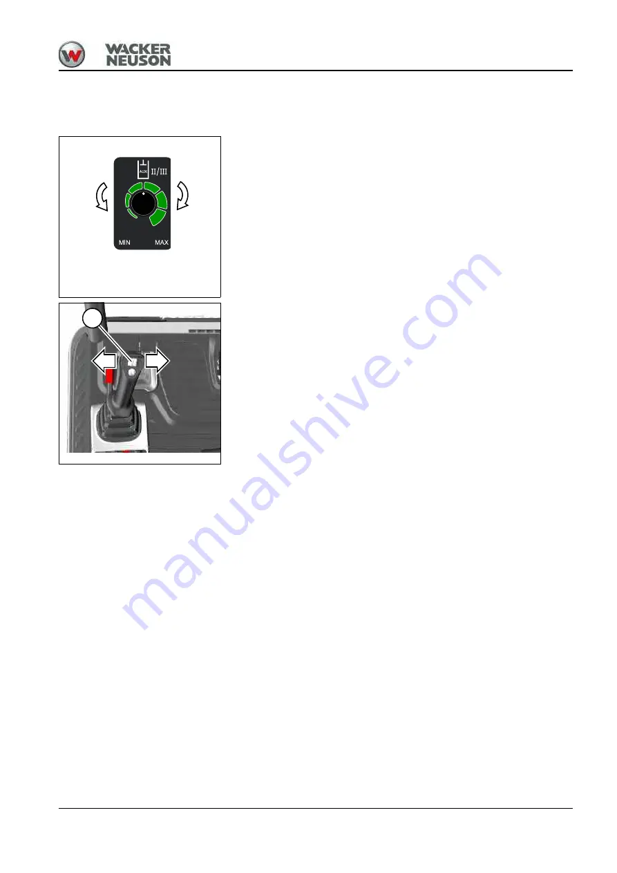
3rd control circuit – AUX II (option)
Turn the rotary switch on the left-hand control lever base to the required
position.
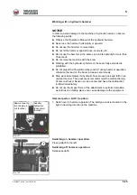
Operating the additional control circuit
Oil flow to left-hand line:
Push slide switch
22
on the left-hand control lever to the left.
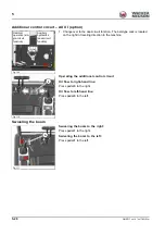
Oil flow to right-hand line:
Push slide switch
22
on the left-hand control lever to the right.
Fig. 115
Fig. 116
22
Summary of Contents for EZ17
Page 12: ...1 6 OM EZ17 us 1 0 ez17v100 fm 1 Notes...
Page 38: ...3 10 OM EZ17 us 1 0 ez17e300 fm 3 Warning labels Fig 11 symbolic representation...
Page 43: ...OM EZ17 us 1 0 ez17e300 fm 3 15 3 Labels Fig 24 symbolic representation...
Page 48: ...3 20 OM EZ17 us 1 0 ez17e300 fm 3 Notes...
Page 138: ...5 56 OM EZ17 us 1 0 ez17b510 fm 5 Notes...
Page 146: ...6 8 OM EZ17 us 1 0 ez17t600 fm 6...
Page 198: ...7 52 OM EZ17 us 1 0 ez17w710 fm 7 Notes...
Page 202: ...8 4 OM EZ17 us 1 0 ez17b800 fm 8 Notes...
Page 222: ...9 20 OM EZ17 us 1 0 ez17t900 fm 9 Dimensions Overview EZ17 Fig 227...


