


5-36
OM EZ17 us 1.0 * ez17b510.fm
5
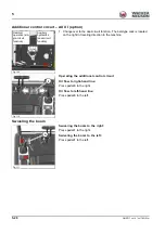
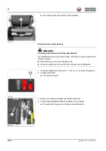
Connecting and disconnecting hydraulic couplings
1. Stop and park the machine. See “Preparing lubrication”.
2. Position the boom straight ahead at the center of the machine.
3. Lower the stabilizer blade to the ground.
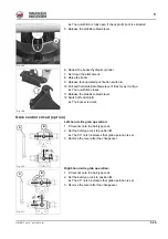
4. Turn the starting key to position
1
.
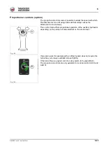
5. Move the control lever or the slide switch of the hydraulic circuit in all
directions repeatedly.
6. Remove the starting key and carry it with you.
➥
The grab hose couplings can now be coupled and uncoupled.
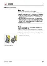
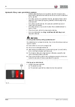
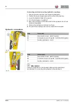
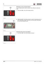
Hydraulic connections
Information
Follow the instructions in the Operator’s Manual of the attachment
manufacturer for connecting the hydraulics to the attachment.
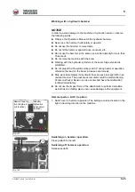
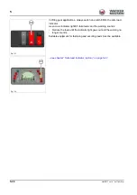
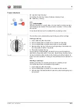
Fig. 132
A
B
C
Port
Stick (left)
A
Grab control circuit – AUX IV (option)
B
3rd control circuit or Powertilt – AUX II/AUX III (option)
C
Auxiliary hydraulics – AUX I
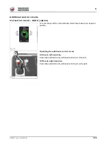
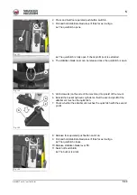
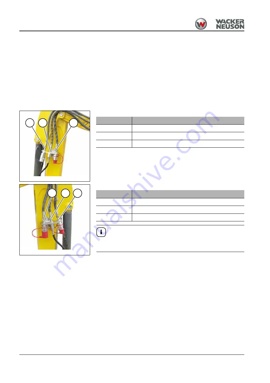
Fig. 133
C
A
B
Port
Stick (right)
A
Grab control circuit – AUX IV (option)
B
3rd control circuit or Powertilt – AUX II/AUX III (option)
C
Auxiliary hydraulics – AUX I
Summary of Contents for EZ17
Page 12: ...1 6 OM EZ17 us 1 0 ez17v100 fm 1 Notes...
Page 38: ...3 10 OM EZ17 us 1 0 ez17e300 fm 3 Warning labels Fig 11 symbolic representation...
Page 43: ...OM EZ17 us 1 0 ez17e300 fm 3 15 3 Labels Fig 24 symbolic representation...
Page 48: ...3 20 OM EZ17 us 1 0 ez17e300 fm 3 Notes...
Page 138: ...5 56 OM EZ17 us 1 0 ez17b510 fm 5 Notes...
Page 146: ...6 8 OM EZ17 us 1 0 ez17t600 fm 6...
Page 198: ...7 52 OM EZ17 us 1 0 ez17w710 fm 7 Notes...
Page 202: ...8 4 OM EZ17 us 1 0 ez17b800 fm 8 Notes...
Page 222: ...9 20 OM EZ17 us 1 0 ez17t900 fm 9 Dimensions Overview EZ17 Fig 227...


