5-8
OM EZ17 us 1.0 * ez17b500.fm
5
5.5
Differential lock
Not available.
5.6
Lights/signaling system
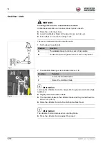
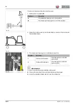
Working lights
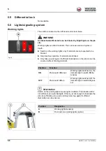
The switch is located on the left-hand control lever base.
WARNING
Accident hazard! Motorists can be blinded by bright lights on the job
site.
Working lights can blind motorists. This can cause serious injuries or
death.
►
Switch on the working lights only if motorists are not expected to be
blinded.
►
Stop machine operation if motorists are blinded.
►
Only take up work again if sufficient illumination on the job site can be
ensured without blinding motorists.
Information
Switch on the working lights in poor light conditions. If illumination still is
not sufficient, use external lights. If this is yet not enough to illuminate the
job site sufficiently, stop work and only take it up again if sufficient
illumination can be ensured.
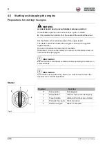
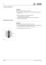
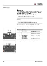
Fig. 86
38
Position
Function
ON
Press switch
38
down
Working lights switched on, the
indicator light in switch
38
illu-
minates
OFF
Press switch
38
up
Working lights switched off, the
indicator light in switch
38
goes
out
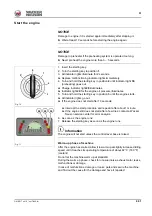
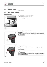
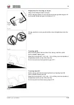
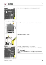
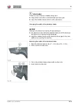
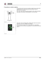
Fig. 87
A
B
Position
Designation
A
Working light (standard)
B
Front and rear working lights (option)
Summary of Contents for EZ17
Page 12: ...1 6 OM EZ17 us 1 0 ez17v100 fm 1 Notes...
Page 38: ...3 10 OM EZ17 us 1 0 ez17e300 fm 3 Warning labels Fig 11 symbolic representation...
Page 43: ...OM EZ17 us 1 0 ez17e300 fm 3 15 3 Labels Fig 24 symbolic representation...
Page 48: ...3 20 OM EZ17 us 1 0 ez17e300 fm 3 Notes...
Page 138: ...5 56 OM EZ17 us 1 0 ez17b510 fm 5 Notes...
Page 146: ...6 8 OM EZ17 us 1 0 ez17t600 fm 6...
Page 198: ...7 52 OM EZ17 us 1 0 ez17w710 fm 7 Notes...
Page 202: ...8 4 OM EZ17 us 1 0 ez17b800 fm 8 Notes...
Page 222: ...9 20 OM EZ17 us 1 0 ez17t900 fm 9 Dimensions Overview EZ17 Fig 227...


