5A-14
5A
G3.3A/G4.6A/GS4.6A/GS5.7A
50 HZ PORTABLE GENERATORS
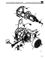
5.19 Generator Assembly
When assembling the generator be sure to observe the
following:
1.
Make sure inner taper on rotor and outer taper on the
engine crankshaft are clean and free of rust and oil.
See Figure 5-16.
2.
Install the rotor
(4)
on crankshaft.
3.
Slide stator
(14)
over the rotor carefully to avoid
hitting and damaging windings. Tap the frame onto
the rotor bearing.
4.
Attach the four nuts
(11)
to secure frame to the
adapter studs
(2)
.
5.
Install the washer and shaft securing nut
(7)
. Tighten
to 13 ft. lbs. (17.5 Nm).
6.
If brushes were changed, reinstall the brushes,
springs and terminal plate.
Note:
New brushes must be seated using a medium
grade abrasive cloth.
7.
Attach AVR
(24)
to brush holder
(23)
using three
mounting screws
(25)
.
8.
Reattach the two leads (Z1 and Z3) to the choke.
Using the two mounting screws
(15)
and
(17)
, install
the diode bridge rectifier
(16)
and choke
(18)
.
9.
Reattach lead to bridge rectifier
(16)
.
10. Install the end cover
(20)
and two mounting screws
(19)
.
11. Reconnect the stator wires
(26)
and
(27)
to the
control panel and reinstall panel.


