GV Generators
Troubleshooting Voltage Issues
wc_tx000772gb.fm
37
2.10 Checking the Anti-Afterfire Solenoid
Prerequisites
Multimeter
Functioning DC Rectifier (See section
Checking Auto Idle Unit and Circuitry.
)
Procedure
Follow the procedure below to check the Anti-Afterfire Solenoid (AAS).
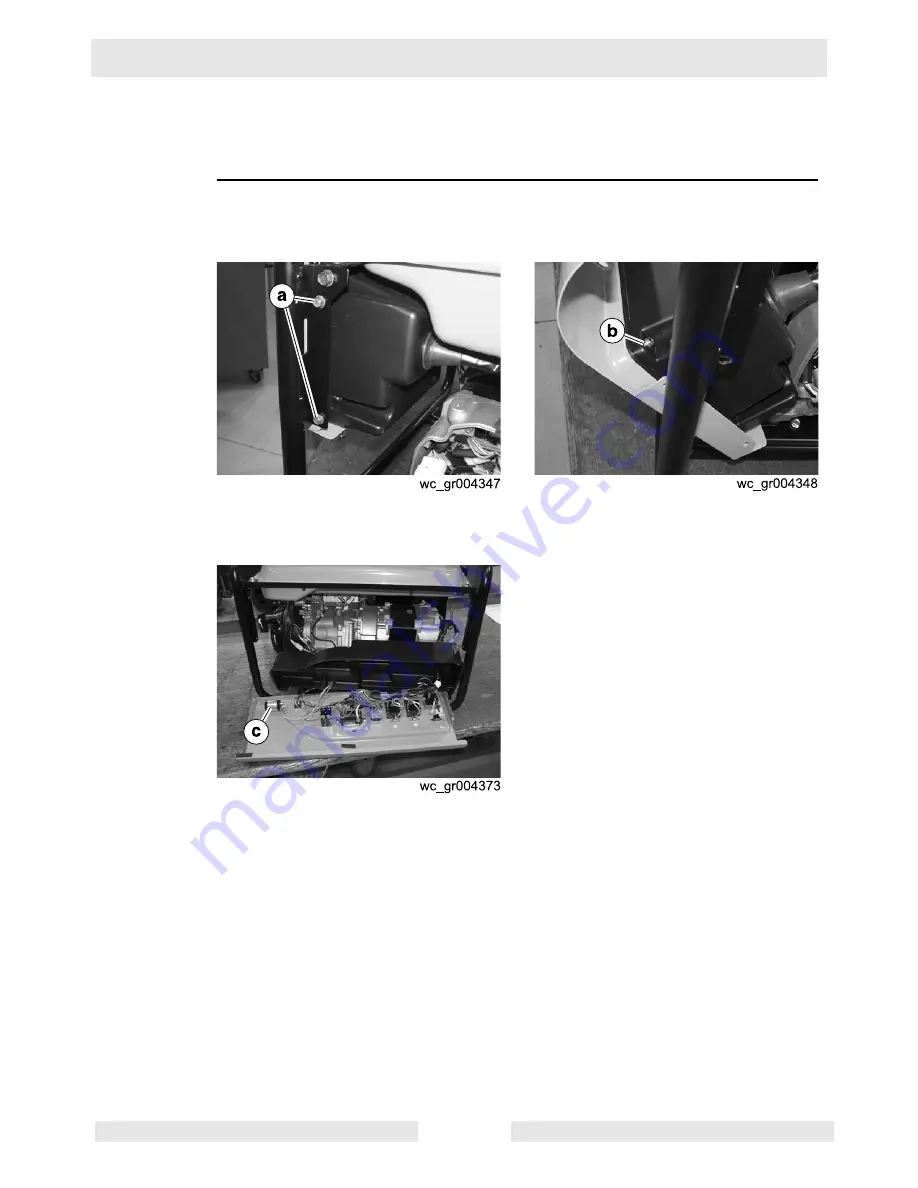
1. Remove the screws
(a)
that secure the control panel to the frame. Once
removed, lower the control panel to access the screws
(b)
.
2. Remove the screws
(b)
that secure the front and back halves of the control
panel.
3. Position the front half of the control panel to access the capacitor
(c)
.
4. Remove the wiring from the capacitor.
5. Discharge the capacitor by placing a screwdriver across the two terminals.
This procedure continues on the next page.


