background image

wc_tx003107gb.fm

95

LTN

Schematics

11 Schematics

11.1

LTN 8K-V Lighting Schematic

17 BK 10 

2

4

1

3

16 BK 10 

23 WH 10 

23 WH 10 

22 GN/YL 10 

22 GN/YL 10 

16 BK 10 

18 BK 10 

19 BK 10 

18 BK 10 

19 BK 10 

3 BK

10 

6 BK 14 

12 BK 14 

14 BK 14 

26 WH 10 

25 BK

10 

24 BK 10 

27 GN/YL 10 

27 GN/YL 10 

8 WH 10 

9 WH 10 

28 BK 10 

29 BK 10 

23 WH 10 

27 GN/YL 10 

22 GN/YL 10 

11 GN/YL 12 

9 WH 10 

8 WH 10 

1 BK 10 

1 GN/YL 12 

12 GN/YL

11 GN/YL 12 

1

2

10 WH 10 

3

4

2 BK 10 

13 BK 10 

1 BK 10 

4 BK 10 

7 BK 10 

6 BK 10 

2

GN

WH

GN

BL

4

PU

WH

BL

WH

BL

11 GN/YL 12 

10 WH 10 

4

BK

RD

GN

WH

GN

BL

1

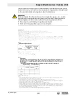
WH

OR

BR

3

BL

YL

GN

2

YL

YL

BK/YL

1

YL

YL

3

BK/YL

BK/YL

PU

YL

YL

WH

8 WH 10 

YL

BK/YL

YL

9 WH 10 

OR

BR

7 BK 10 

6 BK 10 

5 BK

10 

d1

d3

s3

b

o

eg

eg

ff

c

f

t

v

a

b

s1

s2

s4

m

h

mm

m

d2

d4

wc_gr010838

Summary of Contents for LTN 6K-V

Page 1: ...r s Manual Light Tower LTN 6K V LTN 6K VS LTN 8K V LTN 8K VS LTN 6L VS 60 Hz Type LTN 6K V LTN 6K VS LTN 8K V LTN 8K VS LTN 6L VS 60 Hz Document 5200004275 Date 1115 Version 03 Language EN 5 2 0 0 0 0 4 2 7 5 ...

Page 2: ... distribution not authorized by Wacker Neuson Production Americas LLC represents an infringement of valid copyrights Violators will be prosecuted Trademarks All trademarks referenced in this manual are the property of their respective owners Manufacturer Wacker Neuson Production Americas LLC N92W15000 Anthony Avenue Menomonee Falls WI 53051 U S A Tel 262 255 0500 Fax 262 255 0550 Tel 800 770 0957 ...

Page 3: ...requesting parts or service for this machine Machine documentation From this point forward in this documentation Wacker Neuson Production Americas LLC will be referred to as Wacker Neuson Keep a copy of the Operator s Manual with the machine at all times Use the separate Parts Book supplied with the machine to order replacement parts If you are missing either of these documents please contact Wack...

Page 4: ...authorized Wacker Neu son service center according to written instructions published by Wacker Neu son Unapproved parts attachments and modifications are those that do not meet the approved criteria Unapproved parts attachments or modifications may have the following consequences Serious injury hazards to the operator and persons in the work area Permanent damage to the machine which will not be c...

Page 5: ... Label Meanings 22 3 Lifting and Transporting 31 3 1 Lifting the Machine 31 3 2 Preparing the Machine for Transport on a Truck or Trailer 32 3 3 Preparing the Machine for Towing 33 3 4 Towing the Machine 34 4 Operation 35 4 1 Preparing the Machine for First Use 35 4 2 Generator Derating 35 4 3 Positioning the Machine 36 4 4 Ground Connection 37 4 5 Leveling Trailer 38 4 6 Refueling the Machine 39 ...

Page 6: ...enance 59 6 2 Periodic Maintenance Schedule 60 6 3 Cleaning the Machine 61 6 4 Inspecting the Machine 62 6 5 Checking the Engine Oil 63 6 6 Changing the Engine Oil 64 6 7 Checking the Engine Coolant Level 65 6 8 Flushing the Radiator 66 6 9 Cleaning the Air Filter Element 68 6 10 Maintaining the Battery 69 6 11 Checking Fan Belt Tension 70 6 12 Checking Radiator Hoses 71 6 13 Performing Coolant So...

Page 7: ...V LTN 8K V 94 10 7 Dimensions LTN 6K VS LTN 8K VS LTN 6L VS 94 11 Schematics 95 11 1 LTN 8K V Lighting Schematic 95 11 2 Components 96 11 3 LTN 6K V Lighting Schematic 97 11 4 Components 98 11 5 Generator Capacitor Excitation Schematic 99 11 6 Engine Wiring 100 11 7 Components 101 11 8 Hydraulic Schematic LTN 6K V LTN 8K V 102 11 9 Hydraulic Schematic LTN 6K VS LTN 8K VS 103 11 10 Trailer Wiring 1...

Page 8: ...Table of Contents LTN wc_bo5200004275_03TOC fm 8 ...

Page 9: ...ersonal hazards f Obey all safety messages that follow this symbol DANGER DANGER indicates a hazardous situation which if not avoided will result in death or serious injury f To avoid death or serious injury from this type of hazard obey all safety messages that follow this signal word WARNING WARNING indicates a hazardous situation which if not avoided could result in death or serious injury f To...

Page 10: ...r persons in the area Machine damage caused by misuse is not covered under warranty The following are some examples of misuse Connecting a load that has voltage and frequency requirements that are incompatible with the machine output Overloading the machine with a device that draws excessive power during either continuous running or startup Operating the machine in a manner that is inconsistent wi...

Page 11: ...iated with it Operator qualifications Only trained personnel are permitted to start operate and shut down the machine They also must meet the following qualifications have received instruction on how to properly use the machine are familiar with required safety devices The machine must not be accessed or operated by children people impaired by alcohol or drugs Application area Be aware of the appl...

Page 12: ...ther power sources such as supply mains of power companies Never use the machine if the insulation on the electrical cord is cut or worn through Never raise the tower or operate the machine in high winds The tower extends up to 8 7 m 28 54 ft Make sure the area above the trailer is open and clear of overhead wires and obstructions Operation Keep the area under and around the lights clear of people...

Page 13: ...gulation performance standards 21 CFR 1040 30 Operating safety Replace damaged lamps according to the instructions in section Removing Replacing Lamps Alternative lamps that automatically extinguish when the outer envelope is broken or punctured are commercially available WARNING Personal injury hazard Broken or punctured lamps can cause serious skin burns and eye inflammation from shortwave ultra...

Page 14: ...ate the machine with a known problem or deficiency All repairs and adjustments shall be completed by a qualified technician Turn off the machine before performing maintenance or making repairs Remain aware of the machine s moving parts Keep hands feet and loose clothing away from the machine s moving parts Re install the safety devices and guards after repair and maintenance procedures are complet...

Page 15: ...servicing or maintaining this machine Close fitting work clothes that do not hinder movement Safety glasses with side shields Hearing protection Safety toed footwear In addition before servicing or maintaining the machine Tie back long hair Remove all jewelry including rings Before servicing the Light Tower make sure the engine start switch is turned to the OFF position the circuit breakers are op...

Page 16: ...wipe the machine dry before starting Refueling safety When refueling the engine Clean up any spilled fuel immediately Refill the fuel tank in a well ventilated area Replace the fuel tank cap after refueling Use suitable tools for refueling for example a fuel hose or funnel When refueling the engine Do not smoke Do not refuel a hot or running engine Do not refuel the engine near sparks or open flam...

Page 17: ... lift or hold the machine safely See section Technical Data for machine weight Remain aware of the location of other people when lifting the machine Only use the lifting points and tie downs described in the Operator s Manual Make sure the transporting vehicle has sufficient load capacity and platform size to safely transport the machine To reduce the possibility of injury Do not stand under the m...

Page 18: ...erly inflated Only tow the machine when all trailer lights are functioning correctly Only tow the machine when the trailer s safety chains are connected to the towing vehicle in a crisscross pattern Maintain extra distance between the towing vehicle and other vehicles Avoid soft shoulders curbs and sudden lane changes Abide by all licensing requirements for your area If you have not driven a towin...

Page 19: ... an investigation and if it finds that a safety defect exists in a group of trailers it may order a recall and remedy campaign However NHTSA cannot become involved in individual problems between you your dealer or Wacker Neuson To contact NHTSA you may either contact the Vehicle Safety Hotline toll free at 1 888 327 4236 TTY 1 800 424 9153 go to http www safercar gov or write to Administrator NHTS...

Page 20: ...Labels LTN 20 wc_si000705gb fm 2 Labels 2 1 Label Locations wc_gr009301 A B R C C C S W H H X Y D E F G H I J K L Q P O N M ...

Page 21: ...LTN Labels wc_si000705gb fm 21 wc_gr009302 E B A Z EE AA K BB W GG HH W X H II CC JJ FF W DD G ...

Page 22: ...Labels LTN 22 wc_si000705gb fm 2 2 Label Meanings A WARNING Avoid crushing area B NOTICE Lifting point C Fork lift pocket D D Coolant overflow bottle only not a return system 176105 176105 ...

Page 23: ...ion of the tower optional G WARNING Explosion hazard Do not use evaporative starting fluids such as ether on this engine The engine is equipped with a cold starting aid Using evaporative starting fluids can cause an explosion which can cause engine damage personal injury or death Read and follow the engine starting instructions in this Operator s Manual H Tie down point 178775 178775 AVERTISSEMENT...

Page 24: ...SECURE TOWER FOR TRANSPORT 3 Loosen knob 4 Use handle to rotate sets so lights are level 5 Tighten knob 6 Use switch inside door to rotate light bar parallel to machine K WARNING Electric shock and arc flash can cause seri ous injury or death Electrical storage device within Contact a qualified electrician for ser vice or to open electrical box ...

Page 25: ...remolcar evite altas velocidades aceleracion velocidades aceleracion rapida y vueltas agudas rapida y vueltas agudas DANGER DE RETORNEMENT DANGER DE RETORNEMENT AVERTISSEMENT AVERTISSEMENT ADVERTENCIA ADVERTENCIA PELIGRO DE VUELCO PELIGRO DE VUELCO Avoid high speeds rapid Avoid high speeds rapid acceleration and sharp turns acceleration and sharp turns when towing when towing WARNING WARNING ROLL ...

Page 26: ...n the key switch to the START position for a maximum of 15 seconds 3 When the engine is running move the circuit breakers to the ON position TO SHUT DOWN THE MACHINE Move the circuit breakers to the OFF position Turn the key switch to the OFF position to stop the engine O WARNING Operation of this equipment may create sparks that can start fires around dry vegeta tion A spark arrester may be requi...

Page 27: ...h Do not position Light Tower under electrical power lines R Low sulfur fuel or ultra low sulfur fuel only S DANGER No sparks flames or burning objects near machine Stop the engine before adding fuel Use only diesel fuel W Insert jack locking pin before extending jack X CAUTION Wheel nuts must be tightened to 85 ft lbs ...

Page 28: ...tch inside door to rotate light bar perpendicular to machine TO AIM LIGHTS 2 Swivel and tilt lights manually to desired position 3 Loosen knob 4 Use handle to adjust light set to desired position 5 Tighten knob 6 Rotate light bar to desired position TO RAISE TOWER 7 Use switch inside door to raise tower UTILITY 159116 UTILITY 159116 U S PAT Nos 6012285 6471476 U S PAT Nos 6012285 6471476 D416858 D...

Page 29: ...ns cover and fixture FF WARNING Hot surface GG HH GG HH DANGER Using a light tower indoors CAN KILL YOU IN MINUTES Light tower exhaust contains carbon monoxide This is a poison you cannot see or smell NEVER use inside a home or garage EVEN IF doors and windows are open Only use OUTSIDE and far away from windows doors and vents 179213 179213 WARNUNG WARNUNG ADVERTENCIA ADVERTENCIA WARNING WARNING A...

Page 30: ...shing hazards Stand clear of the front of the machine when the tower is being lowered with the hydraulic manual override valve JJ WARNING Hot surface 117039 117039 ADVERTENCIA ADVERTENCIA AVERTISSEMENT AVERTISSEMENT WARNING WARNING WARNUNG WARNUNG ...

Page 31: ...lift the machine 1 Attach the lifting equipment to one of the lifting eyes b on the machine using hooks shackles and chains or insert forks into the fork pockets a 2 Lift the machine a small distance 3 Check for stability If necessary lower the machine reposition the lifting device and lift the machine a small distance again 4 Continue lifting the machine as necessary WARNING Crushing hazard You m...

Page 32: ...trailer can support the weight of the machine Check that the wheels of the transport vehicle or trailer are chocked during the loading process Check that the transport vehicle or trailer is clean and free of grease oil ice and other loose material Do not use the machine s trailer jack to support the trailer tongue during transporting Check that any ramps used in the loading process Can support the...

Page 33: ...hat the towing vehicle and hitch have a rating equal to or greater than the GVWR of the machine See Technical Data Check that the hitch of the towing vehicle and coupler of the trailer are compatible Check the condition of both the coupler and the hitch Check that all fasteners on the coupler are secure Check that the coupler has fresh grease applied to it Wheels Check that all lug nuts are in pla...

Page 34: ...Machine 2 Complete the shut down procedures 3 Adjust the amount of fuel in the machine to approximately 70 capacity to avoid fuel spillage 4 Complete the Before Towing Checklist See topic Before Towing Checklist 5 Connect the machine to the towing vehicle 6 Rotate the trailer and tongue jacks to a horizontal position 7 Tow the machine as needed WARNING Risk of severe injury or death Improperly tor...

Page 35: ...for 4 Attach component parts not already attached 5 Add fluids as needed and applicable including fuel engine oil and battery acid 6 Move the machine to its operating location 4 2 Generator Derating Description All generator sets are subject to derating reduced power output depending on the altitude and ambient temperature Derating should not affect the operation of the floodlights although it wil...

Page 36: ...s doors panels may be accessed so that the area to be illuminated is at or below the level of the lights so that there is room around the machine for the outriggers to be extended DANGER Asphyxiation hazard Exhaust gas from the machine contains carbon monoxide a deadly poison you cannot see or smell Exposure to carbon monoxide can kill you in minutes f Position the machine so that exhaust will not...

Page 37: ...er when necessary to comply with the National Electrical Code and other federal state and local regulations For grounding requirements in your area consult with a qualified electrician electrical inspector or local agency having jurisdiction over electrical compliance If the Light Tower is used at a construction site there may be additional regulations which must be observed wc_gr010503 a ...

Page 38: ...ace 5 Pull the locking pins on the outrigger jacks e Rotate the jacks 90 down Reinsert the pins once the jacks are in position 6 Pull the locking pin on the rear jack f and rotate the rear jack down 90 Reinsert the pin once the jack is in position 7 Extend the jack s on the highest side s of the trailer until they rest firmly on the ground Extend the remaining jacks until the trailer is level WARN...

Page 39: ...level and the top of the tank 3 Reinstall the fuel cap Result The procedure to refuel the machine is now complete WARNING Fire hazard Fuel and its vapors are extremely flammable Burning fuel can cause severe burns f Keep all sources of ignition away from the machine while refueling f Refuel only when the machine is outdoors f Clean up spilled fuel immediately a wc_gr008825 D CAUTION Fire and healt...

Page 40: ...is machine stopped To rotate the lights see topic Rotating the Lights Requirements Before adjusting the lights make sure that the following conditions have been met Machine is stopped Tower is completely lowered Lights are cool to the touch Aiming the light fixtures Aiming Up or Down Perform the procedure below to aim an individual light fixture up or down 1 Loosen the T handle a and aim the light...

Page 41: ...ovement of the fixture NOTICE Do not loosen the nut b Damage to the light fixture may occur 2 If loosened tighten the bracket nut c when the light is aimed properly Note The bracket nut c should be only tight enough so that slight resistance is present when aiming the fixture 3 Repeat steps 1 2 for each remaining light fixture if desired This procedure continues on the next page wc_gr010507 b c c ...

Page 42: ...ng the light bars Perform the procedure below to aim the light bars 1 Loosen the knob d grasp the handles e and tilt the light bar to the desired angle 2 Tighten the knob d when the light bar is in the desired position 3 Repeat steps 1 2 for the other light bar if desired ...

Page 43: ... Ref Description 1 Floodlight control panel f Hour meter 2 Tower control panel g 30A receptacle a 25A main circuit breaker h 30A receptacle breaker b 30A lights circuit breaker i Tower actuation switch c 20A GFI circuit breaker j Tower rotation switch d 20A GFI receptacle k Glow plug indicator e 33A main circuit breaker l Key switch ...

Page 44: ... Amp lights circuit breaker l Alternator indicator c 20 Amp circuit breaker m Auxiliary lights not used d 20 Amp GFI receptacle n Glow plug indicator e Hour meter o Air filter restriction indicator f Low fuel indicator not used p Auxiliary lights not used g Safety shutdown indicator q Key access door h Low oil pressure shutdown indi cator r GFCI circuit breaker wc_gr005141 KOHLER KOHLER e b c d a ...

Page 45: ...racks in the insulation Close and secure access covers before starting the machine Check the engine Check fuel engine oil and coolant levels Add fluids if necessary Verify that the air filter element is clean and undamaged Replace if necessary Check to make sure no debris has lodged in vents near the radiator or around the fan Check to make sure that the exhaust compartment is clean and nothing is...

Page 46: ...e The glow plug indicator will turn off when the engine is preheated NOTICE Cranking the engine longer than 20 seconds could cause damage f If the engine does not start return the key to the OFF position and wait 1 minute for the starter to cool before proceding 2 Immediately rotate and hold the key to the start ST position until the engine starts then release the key 3 Allow the engine to warm up...

Page 47: ...Procedure Follow the procedure below to start the machine 1 Rotate the starting key q one click to the right The glow plug indicator n will illuminate The glow plug indicator will turn off when the engine is preheated 2 Immediately rotate and hold the starting key to the START position until the engine starts then release the key NOTICE Cranking the engine longer than 20 seconds can cause damage I...

Page 48: ...has warmed up Procedure Perform the procedure below to operate the lights 1 Turn on the main circuit breaker a 2 Turn on individual circuit breakers b one at a time Notes Metal halide floodlights require a warm up time of 5 15 minutes before they reach full brightness After turning the lights off a cool down time of 10 minutes is necessary before they can be turned on again wc_gr009327 a b ...

Page 49: ...s 3 Start the engine See topic Starting the Machine 4 Turn on the circuit breakers a b See topic Operating the Lights 5 Press and hold the upper half of the tower switch d Release the switch when the tower reaches the desired height See topic Rotating the Mast for more information WARNING Personal injury hazard Raising or lowering the tower creates situations that if not avoided will cause death o...

Page 50: ... rotate the mast 360 while the tower is lowered Procedure To rotate the mast perform the procedure below 1 Pull out the locking pin a on the bottom of the mast 2 Rotate the mast to the desired position 3 Engage the locking pin a Note Be sure the locking pin seats into a groove on the sprocket ...

Page 51: ...g brake on the trailer is disengaged while the tower is raised it will lower automatically Procedure Perform the procedure below to lower the tower 1 Stop the engine 2 Turn off the circuit breakers a b 3 Press and hold the lower half of the tower switch d Release the switch when the tower is completely lowered WARNING Personal injury hazard Raising or lowering the tower creates situations that if ...

Page 52: ...matic shutdown occurs the engine will stop Return the key switch to the off position to reset the system See Troubleshooting or contact Wacker Neuson Product Support if automatic shutdown frequently occurs 4 18 Stopping the Machine LTN 6K 8K V NOTICE Turn off the lights before stopping the engine Failure to do so will damage the electrical system Procedure Perform the procedure below to stop the m...

Page 53: ...hine without turning off the lights Damage to the electrical generator will occur Procedure Follow the procedure below to stop the machine 1 Remove all connected loads from the machine 2 Turn the circuit breakers a b c off 3 Rotate the starting key q to the OFF position wc_gr009360 q 230VAC b c a ...

Page 54: ...pped with a pressure release valve c This valve enables the tower to be lowered manually If electrical power is lost or the tower switch is inoperable pull the knob on the pressure release valve The hydraulic cylinder will retract and the tower will lower Push the knob to close the valve after the tower is fully lowered WARNING Personal injury hazard Raising or lowering the tower creates situation...

Page 55: ...197 ft 13 gauge 100 m 328 ft This machine generates increased voltage while the lights are reaching full brightness To avoid damaging sensitive electronic equipment do not connect any such devices to the convenience outlet until the machine and lights have been operating for at least ten minutes Each 120V GFI receptacle b is protected by a 20A circuit breaker a Testing a GFI receptacle Before each...

Page 56: ...n Corporation The illustrations shown in this chapter represent typical installations The factory installed options on your machine may look different 5 1 Engine Block Heater The engine block heater includes a block heater a with a cord b The function of the block heater is to heat the engine coolant engine block to improve cold weather engine starting Plug the cord into a 120V power supply 5 2 Ba...

Page 57: ...r Machines with RCBOs have neutral bonded to ground and thus these machines require grounding The RCBO functions as an overcurrent protection device and a current leakage detection device Whenever an overcurrent condition or a current leakage condition exists the RCBO s activation lever springs to the OFF position This opens the circuit If the activation lever springs to the OFF position during us...

Page 58: ...X 320 Watt LED fixtures that require less than 1 second warm up time no maintenace and 100 264 VAC The LED fixtures are rated for use in extreme cold temperatures to 40 F and offer voltage and current protection This feature is offered as a retrofit kit or as a factory installed option wc_gr011912 ...

Page 59: ...w to prepare this machine for maintenance Key switch in the OFF position Circuit breakers in the OFF position Negative terminal on the battery disconnected DO NOT START sign attached to the control panel WARNING A poorly maintained machine can malfunction causing injuries or permanent damage to the machine f Keep the machine in safe operating condition by performing periodic mainte nance and makin...

Page 60: ... Engine oil Check level 3 Fuel Check level 3 Coolant Check level 3 Air filter dust cup Empty dust 3 Battery electrolyte Check level 3 Fan belt Check condition and tension 3 Air filter element Clean Radiator hoses Check condition 3 Intake air hose Check condition and clear obstructions 3 Fuel filter Replace Replace after every 250 hours of operation Engine oil Change Replace after every 250 hours o...

Page 61: ...or and sensitive electronic components Interior Clean the interior of the machine Remove rags containers or other debris from the cabinet Nothing should be stored inside the machine Remove leaves and twigs from the exhaust pipe Wipe interior surfaces clean of oil dust and dirt Exterior Clean the exterior of the machine with clean water and a mild detergent Battery Replace Radiator hoses and clamps...

Page 62: ...l damage dents cracks broken door latches etc Loose or missing fasteners Loose or missing parts Cut or worn insulation on electrical cords Damaged light fixtures or lamps Fluid leaks Restricted air flow at the engine exhaust Problems with the trailer if equipped see Maintaining the Trailer Internal inspection Open the access doors on both sides of the machine Check for Damage to control panels swi...

Page 63: ...lean around the dipstick a 2 Extract the dipstick and check the oil level Maintain the oil level between the two markings on the dipstick 3 Remove the oil filler cap b and add oil as needed When full the oil level will reach the upper mark on the dipstick c NOTICE Do not overfill the machine with oil Overfilling the engine with oil may lead to excessively high operating temperatures 4 Reinstall th...

Page 64: ... legislation Procedure Perform the procedure below to change the engine oil 1 Locate the oil drain hose a at the base of the engine and feed it through the opening at the rear of the light tower cabinet 2 Remove the cap from the oil drain hose 3 Allow the oil to drain into a suitable container 4 Replace the cap on the oil drain hose Return the hose to its stored location 5 Fill the engine crankcas...

Page 65: ...sure Unscrew and remove the radiator cap after the pressure has been released 3 Verify that the coolant level of the radiator is 19 mm 3 4 in below the bottom of the filler neck Add more coolant if necessary to maintain this level NOTICE Do not overfill the radiator The machine will be damaged 4 Inspect the radiator filler cap and seal for damage Clean the radiator filler cap or replace it if nece...

Page 66: ...ation Procedure Perform the procedure below to flush the radiator NOTICE Do not add fluid to the over flow reservoir 1 Open one of the cabinet doors 2 Slowly rotate the radiator cap a counterclockwise to release any remaining system pressure Unscrew and remove the radiator cap after the pressure has been released 3 Place a plastic sheet and container under the radiator This procedure continues on ...

Page 67: ...lose both drain cocks 7 Inspect the radiator filler cap and seal hoses clamps and plugs for damage Replace any damaged parts 8 Fill the radiator to approximately 19 mm 3 4 in below the bottom of the filler neck NOTICE Do not overfill the radiator The machine will be damaged 9 Clean and reinstall the radiator filler cap Result The radiator has now been flushed WARNING Burn hazard Coolant can contai...

Page 68: ...lter element lightly tap it on a hard surface to eliminate all excess dirt Do not blow the paper with compressed air to clean 4 Wipe the inside of the air cleaner housing with a clean dry cloth 5 Set the air filter element inside the air cleaner housing and then reinstall the cover 6 Open the evacuator valve d once a week under ordinary operating conditions or daily if the light tower is being use...

Page 69: ...gulations Battery connections To connect the battery Connect the red positive battery cable to the battery Connect the black negative battery cable to the battery To disconnect the battery Stop the engine Place all electrical switches in the OFF position Disconnect the black negative battery cable from the battery Disconnect the red positive battery cable from the battery Maintaining battery condi...

Page 70: ... of power to the fan Procedure Perform the procedure below to check the fan belt tension and wear 1 Open the access door on the fuel tank side of the machine 2 Inspect the fan belt a for cuts frayed edges tears or glazed surfaces 3 Apply 10 kg 22 lb of force between the fan pulley and alternator If the deflection b is greater than 9 mm 0 35 in the belt tension must be adjusted 4 Replace the fan be...

Page 71: ... hose a supplies coolant to the engine The lower hose b returns coolant to the radiator Procedure Perform the procedure below to check the radiator hoses 1 Inspect each hose for cuts cracks abrasions or bulges Replace the hose if any of these conditions exist 2 Squeeze each hose to check the elasticity A hose in serviceable condition will yield to slight pressure Replace the hose if it appears to ...

Page 72: ...ssure Unscrew and remove the radiator cap after the pressure has been released 2 Dip a coolant test strip into the filler neck and read the pH level NOTICE Do not use plain water or any other liquid as engine coolant Doing so will quickly corrode and permanently damage the coolant system Damage caused by incorrect coolant will not be covered under warranty Result The coolant solution has now been ...

Page 73: ...Level Procedure Perform the following procedure to test the cooling system pressure 1 Slowly rotate the radiator cap a counterclockwise to release any remaining system pressure Unscrew and remove the radiator cap after the pressure has been released 2 Note the rated operating pressure marked on the outside of the radiator cap When this pressure level is reached a relief valve in the cap discharges...

Page 74: ...the radiator cap Observe the pressure reading Result The cooling system pressure has now been tested If Then Pressure holds just below the rated operating pressure marked on the cap radiator cap is acceptable for use Pressure drops or the rated operating pressure cannot be reached radiator cap must be replaced Contact your Wacker Neuson dealer If Then Pressure holds steady there are no leaks in th...

Page 75: ...jury hazard Ultraviolet radiation from the lamps can cause serious skin and eye irritation f Use only undamaged lamps f Use the lamps only with undamaged original equipment lenses and fixtures WARNING Explosion hazard Grease or oil residue on the lamp can cause the outer jacket to burst or shatter Hot flying glass particles can cause personal injury property damage burns or fire f Do not operate t...

Page 76: ...he lens c with the gasket d attached 3 Remove the hardware securing one side of the lamp stabilizer e Once removed swing the lamp stabilizer to the side and unscrew the lamp f Installing the lamp 1 Screw the lamp in firmly but not forcibly to minimize loosening due to vibration Secure it with the lamp stabilizer 2 Install the gasket around the lens and secure the lens to the reflector with the fla...

Page 77: ... After completing the procedures listed above fill the fuel tank completely and add a high quality stabilizer to the fuel Choose a stabilizer that includes cleaning agents and additives designed to coat protect the cylinder walls Make sure the stabilizer you use is compatible with the fuel in your area fuel type grade and temperature range Do not add extra alcohol to fuels which already contain it...

Page 78: ...l safety and environmental regulations pertaining to the disposal of construction equipment Preparation Perform the following tasks to prepare the machine for disposal Move the machine to a protected location where it will not pose any safety hazards and cannot be accessed by unauthorized individuals Ensure that the machine cannot be operated from the time of final shutdown to disposal Drain all f...

Page 79: ...wc_tx003101gb fm 79 LTN 6K 8K V Maintenance ...

Page 80: ...cartridge oil pan depth 90 mm 3 54 in 16 Check of intake air line Every 400 hours Replacement of oil filter cartridge oil pan depth 124 mm 4 88 in 16 Cleaning of water separator Every 500 hours Removal of sediment in fuel tank Cleaning of water jacket radiator interior 17 to 19 Replacement of fan belt 21 Every year Replacement of air cleaner element 19 2 Check of damage in electric wiring and loos...

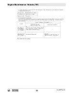
Page 81: ...t temperature below 35 C 95 F Lubricating oil With strict emission control regulations now in effect the CF 4 and CG 4 engine oils have been developed for use with low sulfur fuels for On Highway vehicle engines When a Non Road engine runs on high sulfur fuel it is advisable to use a CF or better classification engine oil with a high Total Base Number a minimum TBN of 10 is recommended Lubricating...

Page 82: ...igh Sulfur Fuels EGR Exh aust Gas Re circulatio n Above 25 C 77 F SAE30 SAE10W 30 or 15W 40 10 to 25 C 14 Fto 77 F SAE10W 30 or 1 5W 40 Below 10 C 14 F SAE10W 30 Fuel typ e Engine oil classification API classificatio n Engines with non E GR Engines with internal EGR Engines with external EG R High Sulfur Fu el 0 05 50 0 ppm Sulfur Content 0 50 500 0 ppm CF If the CF 4 CG 4 CH 4 or CI 4 engine oil ...

Page 83: ...wc_tx003733gb fm 83 Engine Maintenance Kubota T4f ...

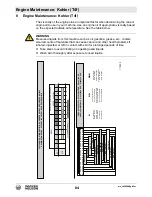
Page 84: ...30 SAE 10W 40 SAE 10W 60 SAE 15W 40 SAE 15W 40 SAE 20W 60 SAE 5W 30 SAE 10W 30 22 30 13 25 4 20 5 15 14 10 23 5 32 0 41 5 50 10 59 15 68 20 77 25 86 30 95 35 104 40 113 45 SAE 10W 122 50 31 35 40 40 Mineral Base Base Minerale Base Minérale Mineralölbasis Base Mineral Base Mineral Semi Synthetic Base Base Semi Sintetica Base Semi Synthétique Halbsynthetische Basis Base Semi Sintetica Base Semi Sint...

Page 85: ...tre à Air à Panneau à Sec Remote Air Filter Dry Type Filtro Aria a Distanza a Secco Filtre à Air à Distance à Sec Combustíveis Fan Alternator Belt Tension Tensione Cinghia Ventola Alternatore Tension Courroie Ventilateur Alternateur Keilriemens Lüfter Tensión Correa Ventilador Alternador Tensão Cincha Ventilador Alternador CHECK CONTROLLO CONTRô LE KONTROLLE COMPROBACìON CONTRô LE ORDINARY MAINTEN...

Page 86: ...rance Registro Gioco Valvole Réglage Jeu Soupapes Einstallen des Ventilspiels Ajuste da Tolarância Registro Juego de Válvulas Apuramento válvula Injector Cleaning and Adjustment Taratura e Pulizia Iniettori Tarage et Nettoyage Injecteur Einspritzdüsen Überprüfen Ajuste y Limpieza Inyectores Taradura e Limpeza Injectores Flush Radiator Pulizia Interna Radiatore Nettoyage Intérieur du Radiateur Inne...

Page 87: ...r Filter Massa Filtrante Filtro Aria a Pannello Masse Filtrante de Filtre à Air á Panneau 10 250 300 500 1000 5000 10000 If you are using oil of a quality lower than the prescribed one then you will have to replace it every 125 hours for the standard sump and every 150 hours for the enhanced sump Se si utilizza olio di qualità inferiore a quello prescritto sostituirlo ogni 125 ore per la coppa sta...

Page 88: ...el lines Clogged fuel filter Replace fuel filter Fuel circuit failure Check fuel lines No generator output Main circuit breaker open Close main circuit breaker Voltage regulator malfunction Call Wacker Neuson for service Low oil pressure Low oil level Fill engine sump with oil Clogged oil filter Replace oil filter Oil pump failure Call Wacker Neuson for service High coolant temperature Electrical ...

Page 89: ...eaker Circuit breaker loose or faulty Repair or replace the circuit breaker Generator output incorrect Check incoming voltage to ballast Incoming voltage should be 120V 5V If voltage is incorrect engine speed may need to be adjusted or generator may require service Low or no ballast output With the fixture cord removed from its receptacle the voltage should measure 400 to 445 VAC If proper voltage...

Page 90: ... D1105 Type 3 cylinder 4 cycle liquid cooled diesel Max rated power rated speed kW hp 9 8 13 1 1800 rpm 11 5 15 4 1800 rpm Operating speed no load rpm 1800 Alternator V A W 12 15 180 Battery V Ah ccA 12 650 Air cleaner type Dry type element Fuel type No 2 diesel Fuel tank capacity L gal 123 32 5 Fuel consumption L gal hr 2 35 0 61 3 07 0 80 Running time hours 53 3 40 6 Coolant capacity L qt 5 78 4...

Page 91: ...iquid cooled diesel Max power rating rated speed kW hp 10 0 13 4 1800 rpm Operating speed no load rpm 1800 Alternator V A W 12 45 540 Battery V Ah ccA 12 650 Air cleaner type Dry type element Fuel type No 2 diesel Fuel tank capacity L gal 123 32 5 Fuel consumption L gal hr 1 71 0 45 Running time hours 67 Coolant capacity L qt 4 7 5 0 Oil specification type AGIP SINT 2000 5W 40 API SJ CF 4 ACEA A3 ...

Page 92: ... 10 3 Generator Machine LTN 6 LTN 8 Frequency Hz 60 Continuous output kW 6 0 8 0 Output volts phase 120 240 1Ø Amps A 50 Excitation type Capacitor Brushless Power factor 1 0 Voltage regulation No load to full load 6 0 Speed no load rpm 1800 ...

Page 93: ...erating weight kg lbs 899 1982 944 2082 1935 878 1985 900 1955 887 2005 909 1945 882 1995 905 Height mast extended m ft 8 7 28 5 8 7 28 5 7 7 25 7 7 25 7 7 25 7 7 25 7 7 25 7 7 25 Output kW 6 8 AC Voltage V 120 240 120 240 Amperage A 50 50 Frequency Hz 60 60 Power factor 1 1 Lamp type Metal halide Metal halide Lamp output W 1000 1000 NEMA beam spread type 6 6 Maximum lighting coverage 0 5 ft candl...

Page 94: ... machine are electric discharge lamps They are designed for use with metal halide ballasts only and require time to reach full brightness on initial startup and after a power interruption These lamps comply with FDA regulation performance standards 21 CFR 1040 30 10 6 Dimensions LTN 6K V LTN 8K V 10 7 Dimensions LTN 6K VS LTN 8K VS LTN 6L VS 120 48 330 130 230 cm in 90 5 wc_gr010809 122 48 318 125...

Page 95: ... 10 8 WH 10 9 WH 10 28 BK 10 29 BK 10 23 WH 10 27 GN YL 10 22 GN YL 10 11 GN YL 12 9 WH 10 8 WH 10 1 BK 10 1 GN YL 12 12 GN YL 11 GN YL 12 1 2 10 WH 10 3 4 2 BK 10 13 BK 10 1 BK 10 4 BK 10 7 BK 10 6 BK 10 2 GN WH GN BL 4 PU WH BL WH BL 11 GN YL 12 10 WH 10 4 BK RD GN WH GN BL 1 WH OR BR 3 BL YL GN 2 YL YL BK YL 1 YL YL 3 BK YL BK YL PU YL YL WH 8 WH 10 YL BK YL YL 9 WH 10 OR BR 7 BK 10 6 BK 10 5 B...

Page 96: ...uit breaker m Capacitors 24 mF d Floodlights o Receptacle 120 240V 30A e Receptacle 120V GFI t Capacitor generator excitation f Circuit breaker 30 Amp v Terminal strip long g Circuit breaker 20 Amp Wire Colors BK Black RD Red YL Yellow OR Orange GN Green TN Tan BR Brown PU Purple BU Blue VIO Violet CL Clear SH Shield PK Pink WH White GY Gray LB Light blue ...

Page 97: ...wc_tx003107gb fm 97 LTN Schematics 11 3 LTN 6K V Lighting Schematic ...

Page 98: ...uit breaker m Capacitors 24 mF d Floodlights o Receptacle 120 240V 30A e Receptacle 120V GFI t Capacitor generator excitation f Circuit breaker 30 Amp v Terminal strip long g Circuit breaker 20 Amp Wire Colors BK Black RD Red YL Yellow OR Orange GN Green TN Tan BR Brown PU Purple BU Blue VIO Violet CL Clear SH Shield PK Pink WH White GY Gray LB Light blue ...

Page 99: ...n Schematic wc_gr011005 COMMON 6 2 2 8 4 3 5 7 1 C1 L1 L1 L2 L3 L3 L4 L4 8 1 120V 60 Hz 115V 50 Hz 120V 60 Hz 115V 50 Hz 240V 60 Hz 230V 50 Hz Ref Description Ref Description 1 Rotor 4 Capacitor 2 Stator 5 Generator Terminal block 3 Excitation coils 6 Control box lights ...

Page 100: ...ring m o n k p b c e i g h a wc_gr011346 L B IG ST B 17 RD 19 RD 16 WH 15 RD 15 RD 16 WH 10 RD 10 RD OR 9 BR 3 RD 9 BR 4 YL 4 YL 3 RD 7 YL 13 BU 14 BK 12 BK 2 OR BK 8 RD 5 RED BK 6 BK 2 3 RD 2 RD j 6 RD 6 RD 18 RD R 5 RD 5 R 20 RD 7 RD 17 4 RD 4 R 1 BK ...

Page 101: ...f Component Ref Component a Bypass relay i Fuel solenoid b Diode j 15A fuse c Glow plug timer k Hour meter d Glow plugs m Battery e Starter n Glow plug indicator f Alternator o Key switch g Oil switch p Float switch containment skid option h Coolant sensor ...

Page 102: ...iption Ref Description a Hydraulic pump c Alarm b Hydraulic valve d Mast switch Wire Colors BK Black RD Red YL Yellow OR Orange GN Green TN Tan BR Brown PU Purple BU Blue VIO Violet CL Clear SH Shield PK Pink WH White GY Gray LB Light blue 1 RD 3 RD 1 RD 3 RD 4 RD a b c d wc_gr010852 a M M ...

Page 103: ... Ref Description a Hydraulic pump c Alarm b Hydraulic valve d Mast switch Wire Colors BK Black RD Red YL Yellow OR Orange GN Green TN Tan BR Brown PU Purple BU Blue VIO Violet CL Clear SH Shield PK Pink WH White GY Gray LB Light blue 3 RD 2 BK 3 RD 4 RD RD RD 1 RD 1 RD 4 RD 2 BK a b d wc_gr012213 ...

Page 104: ...p turn and tail light e License plate light c Side light amber Wire Colors BK Black RD Red YL Yellow OR Orange GN Green TN Tan BR Brown PU Purple BU Blue VIO Violet CL Clear SH Shield PK Pink WH White GY Gray LB Light blue BR GN WH BL RD BL WH WH BL BL WH BL BL BR YL RD BL WH GN YL BR BL BL WH BL BL GN YL BR WH GN RD BL WH c a a e d c d wc_gr005372 ...

Page 105: ......

Page 106: ...i zamiennych skontaktuj się z przedstawicielem firmy Wacker Neuson lub skorzystaj z witryny internetowej http wackerneuson com Důležité upozornění Pro informace o náhradních dílech prosím kontaktujte svého Wacker Neuson dealera nebo navštivte webové stránky http www wackerneuson com FONTOS A pótalkatrészekre vonatkozó információkért kérjük forduljon Wacker Neuson kereskedőjéhez vagy látogasson el ...

Reviews: