background image

Service Electrical Components Safely

!

 WARNING

Always disconnect the negative terminal first
and positive terminal last. Connect positive
terminal first and negative terminal last. Use
care when testing live circuits to prevent
arcing. Arcing could result in death or serious
injury.

Make sure circuit breakers are open (off).

Disconnect the battery negative (–) cable before
removing or installing electrical components.
Always connect the battery negative (–) cable last.

Certain test and adjustment procedures must be
performed with the battery connected. Use care to
prevent arcing when working on live circuits or
components. Arcing can cause component
damage and could ignite flammable materials.

Dispose of Waste Materials Safely

Routine service can produce waste products such as
used oil, coolant, grease, and batteries. If not handled
properly, these materials can pose a threat to the

environment. Collect fluids in well-marked, approved
storage containers. Some waste fluids can react with
certain types of plastics. Make sure the fluid to be stored
is compatible with the storage container. Never use food
or beverage containers to store waste fluids.

NOTICE

Dispose of waste fluids properly at
approved local recycling centers. If
recycling facilities are not available,
contact your local community for the
correct disposal procedure for waste
fluids.

Dispose of old batteries properly. Battery
electrolyte contains sulfuric acid and
other hazardous materials. Never place
an old battery in the trash. Batteries must
be disposed of in a manner consistent
with EPA and/or local regulations.


FOREWORD 

5100048604 (12-18)

9

Summary of Contents for PT Series

Page 1: ...PT Series Trash Pump Service Manual www wackerneuson com Type PT2 PT3 PT4 Document 5100048604 Date 0121 Revision 0 2 Language EN US...

Page 2: ...distribution not authorized by Wacker Neuson America Corporation represents an infringement of valid copyrights Violators will be prosecuted Trademarks All trademarks referenced in this manual are the...

Page 3: ...l diagnostics and repair Make use of special information features within this manual in order to be better prepared to perform repairs Always follow manual procedures and safety guidelines Never take...

Page 4: ...ol down time after pump is shut off Avoid contact with hot parts Retainer pins can fly out or splinter when struck with force Use a brass hammer or a suitable material between the hammer and pin To re...

Page 5: ...hazardous situation which if not avoided COULD result in death or serious injury CAUTION Indicates a potentially hazardous situation which if not avoided MAY result in minor or moderate injury and pro...

Page 6: ...re often used along with safety glasses to offer a higher level of protection when sparks and flying debris are present Vented Goggles Goggles offer side protection not offered by safety glasses alone...

Page 7: ...is strong enough to handle the load When using a lifting device always connect the load so it is balanced Always use a lifting device on a hard level surface Lower the lifting device to the lowest po...

Page 8: ...iners should be stored in an approved safety cabinet away from possible sources of ignition Storage areas and cabinets should be well ventilated to prevent the possible build up of fumes Handle Chemic...

Page 9: ...e Materials Safely Routine service can produce waste products such as used oil coolant grease and batteries If not handled properly these materials can pose a threat to the environment Collect fluids...

Page 10: ......

Page 11: ...Table of Contents Specification and General Information Maintenance Troubleshooting 1 2 3 5100048604 12 18 11...

Page 12: ......

Page 13: ...Chapter 1 Specification and General Information Standard Torque Values 1 2 Torque Values 1 2 General Specifications 1 6 General Specifications 1 6 1 5100048604 12 18 1 1...

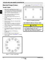
Page 14: ...a Lubricate threads of fasteners as specified in work procedure or Table 2 b Tighten fasteners above 30 lb ft 41 N m using torque pattern and tighten to 70 percent of final value c Multiply final val...

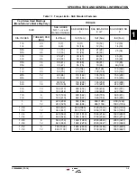
Page 15: ...5 88 75 102 110 149 120 163 135 183 150 203 150 203 170 230 5 8 5 8 11 18 90 122 100 136 150 203 180 244 190 258 210 285 220 298 240 325 3 4 3 4 10 16 160 217 180 244 260 353 300 407 320 434 360 488 3...

Page 16: ...140 190 258 M16 M16 X 1 5 103 140 110 149 148 201 157 213 300 407 M18 M18 X 1 5 147 199 165 224 203 275 320 434 410 556 M20 M20 X 1 5 208 282 213 289 288 390 320 434 580 786 M22 M22 X 1 5 283 384 315...

Page 17: ...l length through which force is applied to fastener TW Torque applied at end of torque wrench TS TE LW LW LE TS Torque wrench setting TE Torque specified at fastener LW Length of torque wrench LE Leng...

Page 18: ...PT3 PT4 Connection Diameter 2 in 50 mm 3 in 80 mm 4 in 100 mm Connection Thread Parallel Pipe Thread or NPT Total Head 98 ft 30 m 89 ft 27 m 98 ft 30 m Discharge Volume 185 gal min 700 L min 383 gal...

Page 19: ...SPECIFICATION AND GENERAL INFORMATION 1 5100048604 12 18 1 7...

Page 20: ...Page Intentionally Blank SPECIFICATION AND GENERAL INFORMATION 1 1 8 5100048604 12 18...

Page 21: ...and Testing 2 2 Engine Oil Drain Fill Procedure 2 2 Pump Priming and Operation 2 3 After Use 2 4 Front Cover 2 5 Suction Test 2 6 Suction and Discharge Flange 2 7 Spark Plug Inspection 2 7 Mechanical...

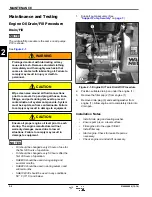
Page 22: ...ue to low oil situations Failure to comply may result in damage to equipment NOTES Oil should be changed every 8 hours of use for the first 20 hours of operation Oil should be changed every 50 hours a...

Page 23: ...secure before operating the pump A loose discharge hose may cause the hose to slip or become detached Failure to comply may result in injury or death to personnel CAUTION Inspect pump and associated a...

Page 24: ...amage to equipment 2 Prime pump See Priming Pump on page 2 3 3 Submerge strainer at the end of the suction hose in water Ensure the strainer is suspended above any dirt or debris that may be at the bo...

Page 25: ...Installation on page 2 5 Front Cover Removal and Installation NOTE All front covers are removed the same way PT4 is shown See Figure 2 4 WARNING High temperatures and or pressures may be caused during...

Page 26: ...sent and undamaged YES Proceed to Step 7 NO Missing or damaged packing Replace packing 7 Inspect suction hose for holes crushing or any other damage Is suction hose free of holes crushing or damage YE...

Page 27: ...discharge flange 1 from pump 3 Installation Notes Install discharge flange by reversing the order of removal Ensure discharge flange seal is undamaged prior to installation Torque discharge flange mo...

Page 28: ...d in a similar fashion PT4 is shown See Figures 2 8 through 2 11 WARNING High temperatures and or pressures may be caused during priming or operation If high temperatures and or pressure conditions ex...

Page 29: ...the mechanical seal 4 from impeller 3 Figure 2 11 Pump Mechanical Seal Removal and Installation 7 Use two suitable tools to evenly pry the machine seal 5 away from the pump 2 Installation Notes Instal...

Page 30: ...Page Intentionally Blank MAINTENANCE 2 2 10 5100048604 12 18...

Page 31: ...Chapter 3 Troubleshooting Troubleshooting 3 2 Starting Engine 3 2 Pump Functions 3 3 Oil Leak 3 4 3 5100048604 12 18 3 1...

Page 32: ...gine Does Not Start Probable Cause Remedy Old Fuel Replace fuel Faulty or Wet Spark Plug Replace or clean spark plug as needed See Spark Plug Inspection on page 2 7 Engine Oil Level is Too High or Too...

Page 33: ...ront Cover on page 2 5 Broken or Damaged Impeller Replace impeller See Mechanical Seal on page 2 8 Symptom Pump Does Not Prime Probable Cause Remedy Air Leak At Suction Hose Repair or replace suction...

Page 34: ...en Tipped Over Clean or replace the following air cleaner carburetor muffler spark plug A separate engine manual prepared by the engine manufacturer is supplied with this machine Refer to the engine m...

Page 35: ...hanical Seal Inspection 2 8 Removal and Installation 2 8 O Oil Leak Symptom Oil Leaks From Muffler or Air Cleaner 3 4 P Pump Functions Symptom Pump Does Not Prime 3 3 Symptom Pump Has Low Delivery Vol...

Page 36: ......

Page 37: ...Notes...

Page 38: ...Wacker Neuson America Corporation N92W15000 Anthony Avenue Menomonee Falls WI 53051 U S A Tel 262 255 0500 Fax 262 255 0550 Tel 800 770 0957...

Reviews: