Drive System
RD 12/RD 12A
wc_tx000667gb.fm
48
5
Drive System
Background
The hydraulic system is powered by two pumps (exciter and drive) mounted in tandem—
connected along their shafts through a solid-mounted coupling—and driven directly by the
engine crankshaft through a flex coupling.
Drive Pump
The drive pump is a variable displacement, axial piston pump and includes an integral
charge pump.
Flow through the drive pump is controlled by varying its displacement through the move-
ment of the control lever coupled to the pump’s control shaft. This allows a full range of
operating speeds in both forward and reverse.
The drive pump includes pressure test ports for the drive system.
The drive pump also includes the towing valve which, when open, allows oil flow to
bypass the drive motors.
Drive Motors
There are two drive motors—one mounted to each drum.
The drive motors are plumbed in series.
System filters
and strainers
The hydraulic tank is equipped with a strainer at the fill port to trap large objects or parti-
cles which may accidentally fall into the tank while adding hydraulic fluid.
Additional system protection is provided by a suction filter mounted in-line with the
exciter pump inlet.
The hydraulic system is protected by a return-line filter which removes dirt particles
down to 10 microns and includes a flow bypass for cold weather start-up.
Troubleshoot-
ing sequence
When troubleshooting drive system problems, do so in the following sequence:
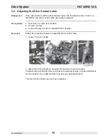
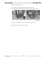
1. Check the tow (bypass) valve.
2. Check the function of the drive control cable.
3. Pressure test the drive pump and relief valve.
4. Check the drive motors for binding.
5. Check the oil flow through the drive motors.
Summary of Contents for RD 12A
Page 1: ...5000192242 02 0912 5 0 0 0 1 9 2 2 4 2 Repair Manual Roller RD 12 EN...
Page 15: ...RD 12 RD 12A Safety Information wc_si000302gb fm 15 1 4 Label Locations X FF...
Page 21: ...RD 12 RD 12A Safety Information wc_si000302gb fm 21 Notes...
Page 25: ...RD 12 RD 12A Operation wc_tx000865gb fm 25 53 47 54 61 50 62 55 wc_gr004114 56...
Page 29: ...RD 12 RD 12A Operation wc_tx000865gb fm 29 wc_gr002951 N F R 55 42 44 54 10 15...
Page 119: ...RD 12 RD 12A Disassembly Assembly wc_tx000671gb fm 119...
Page 120: ...Schematics RD 12 RD 12A wc_tx001073gb fm 120 10 Schematics 10 1 Hydraulic Schematic...
Page 122: ...Schematics RD 12 RD 12A wc_tx001073gb fm 122 10 4 Electrical Schematic A RD 12A...
Page 124: ...Schematics RD 12 RD 12A wc_tx001073gb fm 124 10 6 Electrical Schematic B RD 12A...
Page 126: ...Schematics RD 12 RD 12A wc_tx001073gb fm 126 10 8 Electrical Schematic RD 12...
Page 137: ......


