Disassembly & Assembly
RD 12/RD 12A
wc_tx000671gb.fm
80
Continued from the previous page.
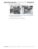
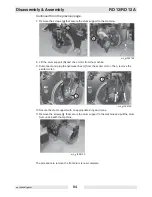
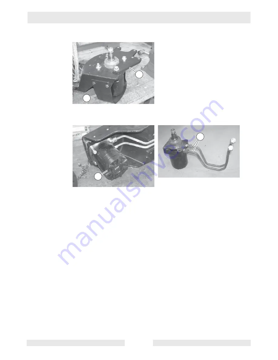
6. Remove the motor guard
(g)
.
7. Remove the brake bracket
(h)
.
8. Remove the drive motor
(i)
from the drum support.
9. Remove the hydraulic lines
(j)
and fittings from the drive motor if not already removed.
The procedure to remove the rear drive motor is now complete.
wc_gr004219
g
h
wc_gr004220
i
j
Summary of Contents for RD 12A
Page 1: ...5000192242 02 0912 5 0 0 0 1 9 2 2 4 2 Repair Manual Roller RD 12 EN...
Page 15: ...RD 12 RD 12A Safety Information wc_si000302gb fm 15 1 4 Label Locations X FF...
Page 21: ...RD 12 RD 12A Safety Information wc_si000302gb fm 21 Notes...
Page 25: ...RD 12 RD 12A Operation wc_tx000865gb fm 25 53 47 54 61 50 62 55 wc_gr004114 56...
Page 29: ...RD 12 RD 12A Operation wc_tx000865gb fm 29 wc_gr002951 N F R 55 42 44 54 10 15...
Page 119: ...RD 12 RD 12A Disassembly Assembly wc_tx000671gb fm 119...
Page 120: ...Schematics RD 12 RD 12A wc_tx001073gb fm 120 10 Schematics 10 1 Hydraulic Schematic...
Page 122: ...Schematics RD 12 RD 12A wc_tx001073gb fm 122 10 4 Electrical Schematic A RD 12A...
Page 124: ...Schematics RD 12 RD 12A wc_tx001073gb fm 124 10 6 Electrical Schematic B RD 12A...
Page 126: ...Schematics RD 12 RD 12A wc_tx001073gb fm 126 10 8 Electrical Schematic RD 12...
Page 137: ......

