RD 12/RD 12A
Disassembly & Assembly
wc_tx000671gb.fm
93
9.19 Disassembling the Exciter Bearings
Prerequisites
Front drum removed
Puller
Procedure
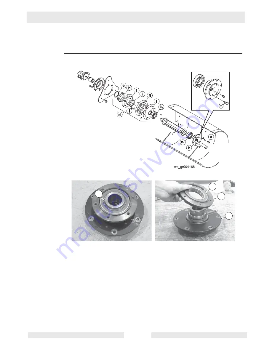
On the exciter side of the drum, two bearings and their flanges make up the drum hub
(d)
.
Follow the procedure below to disassemble the exciter bearings.
1. Remove the retaining ring
(e)
.
2. Use a puller to pull the smaller bearing flange
(f)
and bearing
(h)
from the shaft of the
larger bearing flange
(g)
. Then, use a press to press out the bearing
(h)
from the smaller
bearing flange.
This procedure continues on the next page.
wc_gr004169
e
h
f
g
Summary of Contents for RD 12A
Page 1: ...5000192242 02 0912 5 0 0 0 1 9 2 2 4 2 Repair Manual Roller RD 12 EN...
Page 15: ...RD 12 RD 12A Safety Information wc_si000302gb fm 15 1 4 Label Locations X FF...
Page 21: ...RD 12 RD 12A Safety Information wc_si000302gb fm 21 Notes...
Page 25: ...RD 12 RD 12A Operation wc_tx000865gb fm 25 53 47 54 61 50 62 55 wc_gr004114 56...
Page 29: ...RD 12 RD 12A Operation wc_tx000865gb fm 29 wc_gr002951 N F R 55 42 44 54 10 15...
Page 119: ...RD 12 RD 12A Disassembly Assembly wc_tx000671gb fm 119...
Page 120: ...Schematics RD 12 RD 12A wc_tx001073gb fm 120 10 Schematics 10 1 Hydraulic Schematic...
Page 122: ...Schematics RD 12 RD 12A wc_tx001073gb fm 122 10 4 Electrical Schematic A RD 12A...
Page 124: ...Schematics RD 12 RD 12A wc_tx001073gb fm 124 10 6 Electrical Schematic B RD 12A...
Page 126: ...Schematics RD 12 RD 12A wc_tx001073gb fm 126 10 8 Electrical Schematic RD 12...
Page 137: ......


