TECHNICAL DATA
41
W L 30
3
TECHNICAL DATA
3.1
Technical description
The loader consists of the vehicle frame, the drive and the
axles. The vehicle frame contains all the drive and control
units for the standard configuration. The vehicle frame con
-
sists of the front carriage with the loader lift arms, and the
rear carriage, in which the drive unit is situated. They are
connected by an articulated swivel joint.
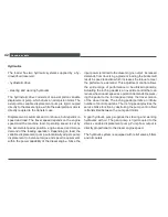
Drive
The loader is driven by a diesel engine, which powers the
steering and working hydraulics and the driving hydraulics.
The propulsion hydraulics provide power to the transfer
gear box by a directly attached hydraulic motor. The rear
axle is integral with the transfer gear box. The front axle is
powered by a driveshaft connecting the transfer gear box
to the front axle.
The axles are designed as rigid axles.
Brakes
Service braking is provided by the propulsion hydraulic
system through the transfer gearbox and driveshaft to both
axles. The braking-inching pedal provides a secondary ser-
vice brake by contacting a hub-mounted differential in the
transfer gear box. A separate parking brake with separate
control is provided that engages the differential hub in the
transfer gear box.
Steering
The fully hydraulic articulated swivel steering system oper-
ates via a dual action cylinder.
Summary of Contents for WL 30
Page 1: ...www wackerneuson com Operator s Manual Wheel Loader WL 30...
Page 2: ...December 10 Edition...
Page 17: ...BASIC INFORMATION 15 WL30...
Page 48: ...TECHNICAL DATA 46 3 4 Dimensions Fig 11 Dimensions...
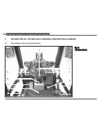
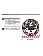
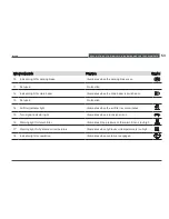
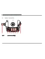
Page 61: ...Description of the indicator warning and control elements 59 WL30...
Page 126: ...Towing and transporting 124 Fig 58 Tying down the loader...
Page 161: ...SERVICING AND INSPECTION 159 WL30 2 1 Fig 63 Cab tilt lever...
Page 235: ...Appendix 233 WL30 For personal notes...
Page 245: ...List of figures 243 WL30...

