


OPE R ATINg A ND OPE R ATION
94
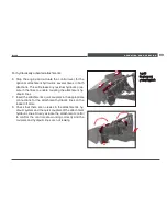
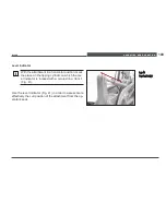
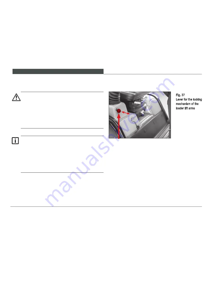
Apply the locking system for the loader lift arm by shifting
the lever located to the right of the operator’s seat Item 1
(Fig. 37).
•
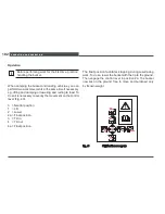
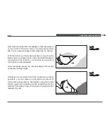
Push the switching control rearward toward the seat
frame:
–
the locking system is now on.
•
Pull the switching control forward away from the seat
frame:
–
the locking system is now off.
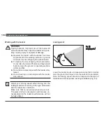
5.4.3 Loader lift arms locking system
•
Before traveling from worksite to worksite over
extended distances, engage the loader lift arm
lock after selecting the height for the travel arms
for the travel segment.
•
Do not release the loader lift arm lock until start-
ing the work cycle, or after parking the loader
and prior to lowering the lift arms to the ground
with the attachment.
The loader lift arm can be secured against uninten-
tional operation by means of a locking mechanism.
If you have switched on the locking mechanism, the
loader lift arms will not move if the loader controls
are moved. The fact that the loader lift arm is locked
is not shown via indicator lights, but instead can
be seen from the position of the switching lever
(Fig. 36).
Fig. 37
Lever for the locking
mechanism of the
loader lift arms
1
Summary of Contents for WL 30
Page 1: ...www wackerneuson com Operator s Manual Wheel Loader WL 30...
Page 2: ...December 10 Edition...
Page 17: ...BASIC INFORMATION 15 WL30...
Page 48: ...TECHNICAL DATA 46 3 4 Dimensions Fig 11 Dimensions...
Page 61: ...Description of the indicator warning and control elements 59 WL30...
Page 126: ...Towing and transporting 124 Fig 58 Tying down the loader...
Page 161: ...SERVICING AND INSPECTION 159 WL30 2 1 Fig 63 Cab tilt lever...
Page 235: ...Appendix 233 WL30 For personal notes...
Page 245: ...List of figures 243 WL30...


