INTERCEPTORS
5
Wade
Drains
‐
11910
CR492,
Tyler,
TX,
75706
‐
Phone:
800
‐
638
‐
9537
Fax:
888
‐
879
‐
9233
‐
www.wadedrains.com
3
‐
29
‐
17
FLOW CONTROL
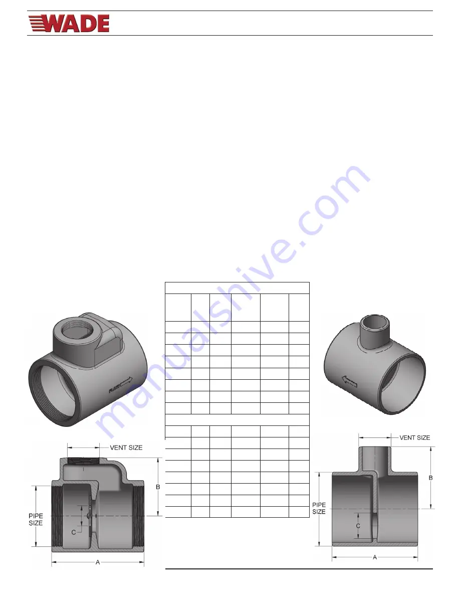
The flow control device is designed with an integral orifice to achieve a predetermined optimum flow rate, thus
eliminating turbulence and to regulate surges in the drainage line. The orifice opening in the flow control device is related
to the size and flow rating of the grease interceptor. The standard orifice sizes are for gravity flow conditions where no
pressure buildup is anticipated. If an interceptor is operating at maximum flow levels, a pressure head may develop,
which may cause an overload condition.
Using the supplied flow control device is an important factor in the operation of the grease interceptor. The flow control
device must be installed in the waste line upstream of the grease interceptor. Typically, the device is placed beyond the
last connection from the fixture(s) and as close as possible to the underside of the lowest fixture. When two or more
sinks or fixtures are combined and served by a single interceptor, a single flow control may be used.
The supplied flow control device must be properly vented to permit air to mix with the fluid entering the interceptor. Air
facilitates the separation and, more Importantly, is necessary to maintain optimum pressure, thereby maintaining the
proper operating level within the interceptor chamber.
The flow control air intake may terminate under the sink drain board as high as possible, to prevent overflow. Another
method is to terminate the vent outside the building. It is recommended that the installer check with the local plumbing
code authority.
VENTING
Grease interceptors must have a vented waste, sized in accordance with code requirements for venting traps, to retain a
water seal and to prevent siphoning.
Flow
Rate
Pipe
Size
Vent
Size
A B
C
4
2”
1 1/4” 3 15/16” 2 11/16” .500
7
2”
1 1/4” 3 15/16” 2 11/16” .688
10
2”
1 1/4” 3 15/16” 2 11/16” .844
15
2”
1 1/4” 3 15/16” 2 11/16” 1.000
20
3”
1 1/2” 5 5/16”
3 11/32” 1.156
25
3”
1 1/2” 5 5/16”
3 11/32” 1.313
35
4”
2”
6 11/16” 4 11/32” 1.500
50
4”
2”
6 11/16” 4 11/32” 1.875
FC-NH
4
2”
1 1/2” 5 1/16”
2 1/2”
.500
7
2”
1 1/2” 5 1/16”
2 1/2”
.688
10
2”
1 1/2” 5 1/16”
2 1/2”
.844
15
2”
1 1/2” 5 1/16”
2 1/2”
1.000
20
3”
1 1/2” 5 1/16”
3 1/4”
1.156
25
3”
1 1/2” 5 1/16”
3 1/4”
1.313
35
4”
1 1/2” 5 1/16”
3 11/16” 1.500
50
4”
1 1/2” 5 1/16”
3 11/16” 1.875
FC-IPS


