background image

INTERCEPTORS


8


Wade


Drains

 ‐ 

11910


CR492,


Tyler,


TX,


75706

 ‐ 

Phone:


800

638

9537


Fax:


888

879

9233

 ‐ 

www.wadedrains.com


3

29

17


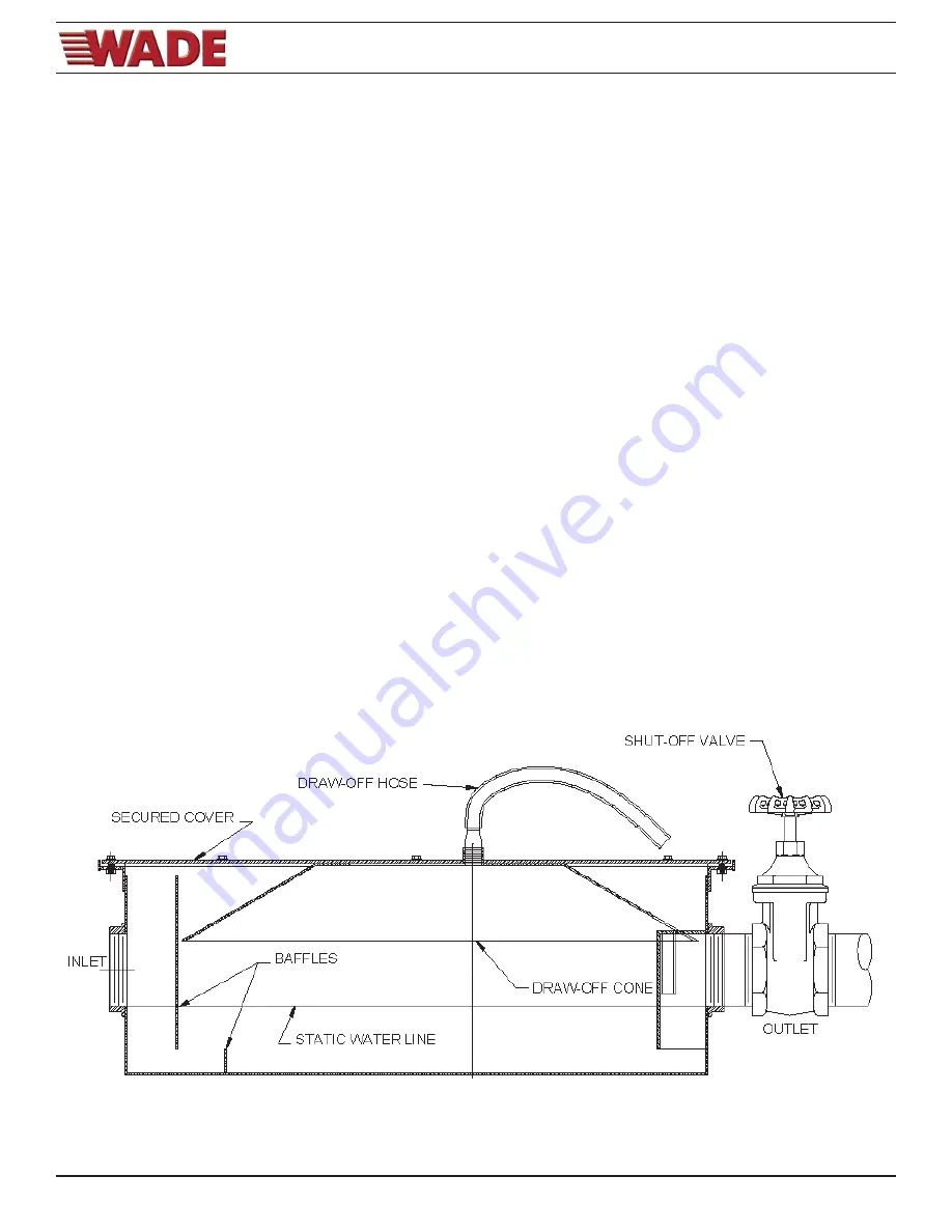
Cleaning (5103 Series) Semi-Automatic Interceptor 

To assist in the maintenance and cleaning process, Wade offers a unit incorporating a top draw-off port for grease 
removal. The cover has an accumulating hood to capture the liquid grease and funnel into the draw off port.  Cleaning 
can easily be performed by following the steps listed: 

1.  The interceptor in normal use has the control valve off and the drain port plugged. When cleaning is required, run a 

full stream of hot water through a fixture serviced by the interceptor. This will liquefy the grease for extraction. A 
period of two minutes is required. 

2.  With the hot water supply shut off, turn the in-line closure valve to a fully closed position. 

3.  Remove the bronze plug from the cover and insert the hose fitting and flexible draw off hose, tightening the hose 

fitting securely. Place the end of the hose into a container suitable for disposal. 

4.  Turn the hot water supply back on back on and allow the water pressure to steadily force the liquefied grease 

through the hose. Caution: The liquid grease may be hot when exiting the draw-off hose; take care to keep the water 
flow as laminar as possible to prevent grease spilling. 

5.  Once grease is no longer visible at the discharge end, turn the water supply off. Properly dispose of the grease. 

Never dispose of the contents in any part of the plumbing system. 

6.  Remove the draw-off hose and fitting and replace the bronze plug. 

7.  Fully open the in-line control valve. 

8.  Periodic inspections of the flow control orifice are suggested. 

9.  A bi-annual inspection of the internals of the interceptor is recommended. Inspect and clean the baffle assembly and 

thourghly clean the body of all solids and debris. 

Summary of Contents for 5100

Page 1: ... prevent odor from escaping An air relief is provided to eliminate siphonage and each unit is furnished with a flow control device to insure it will perform to its rated capacity OPERATION Waste water draining to the interceptor passes through the flow control device which regulates the velocity to a controlled rate As water enters the interceptor the baffle arrangement reduces turbulence to allow...

Page 2: ...17 1 4 14 23 1 4 4 1 2 108 0 35 70 28 6 22 1 2 28 3 4 20 17 1 4 18 25 3 4 4 1 2 129 0 50 100 37 4 22 1 2 30 24 21 1 4 18 27 1 4 4 1 2 151 0 75 150 57 1 23 3 8 34 5 8 30 5 8 27 7 8 17 1 2 31 7 8 5 7 8 156 0 100 200 106 2 27 5 8 41 3 8 35 5 8 32 7 8 22 38 5 8 5 5 8 172 0 Wt Lbs 4 8 4 4 10 1 2 18 13 10 25 7 15 1 4 3 1 2 40 0 Size GPM Suffix Op ons HD Heavy Duty Cover 24 Anchor Flange 26 Anchor Flange w...

Page 3: ...INTERCEPTORS 3 Wade Drains 11910 CR492 Tyler TX 75706 Phone 800 638 9537 Fax 888 879 9233 www wadedrains com 3 29 17 5100 Grease Interceptor ...

Page 4: ...duce the rated efficiency of the interceptor In an application where solids will be present a solids interceptor should be used A separate grease interceptor is recommended for each commercial dishwasher The size is determined by the discharge rate of the dishwasher as stated by the manufacturer Placement of a grease interceptor in a high traffic area is an important concern If the unit is to be i...

Page 5: ... single flow control may be used The supplied flow control device must be properly vented to permit air to mix with the fluid entering the interceptor Air facilitates the separation and more Importantly is necessary to maintain optimum pressure thereby maintaining the proper operating level within the interceptor chamber The flow control air intake may terminate under the sink drain board as high ...

Page 6: ... time thus allowing these particles to pass through the interceptor Increasing the size of the interceptor will allow longer retention rates and improve the efficiency Flow Capacity If maximum recommended flow rates are exceeded the efficiency of the interceptor will be decreased Either install additional flow controls devices at all sources of flow or install a larger interceptor Specific Gravity...

Page 7: ...r the unit has been in operation for several weeks A logical cleaning schedule is normally determined by checking the unit after a normal shift or following a period of peak usage Grease removal intervals may vary from once a week to once in several weeks Never clean an interceptor during a time when customers are present as the offensive odors may develop inside the interceptor Cleaning can easil...

Page 8: ... position 3 Remove the bronze plug from the cover and insert the hose fitting and flexible draw off hose tightening the hose fitting securely Place the end of the hose into a container suitable for disposal 4 Turn the hot water supply back on back on and allow the water pressure to steadily force the liquefied grease through the hose Caution The liquid grease may be hot when exiting the draw off h...

Page 9: ...xtension is specified by expanding the H dimension on the interceptor The H dimension is from the center of the inlet and outlet to the top of the interceptor One would specify a H dimension to meet the job requirements and the interceptor will be manufactured to that specification The extension is incorporated into the production of the interceptor to produce a seamless integral interceptor A sec...

Page 10: ...uations occur The extension is adjustable and is secured to the interceptor similar to a fixed extension After bolting the extension to the interceptor the top is adjustable to grade Installation Note If adjustable extension is install in areas other than on grade where fumes may seep from the adjustable extension connections an optional rope seal is recommended The 1 2 diameter neoprene sponge ga...

Reviews: