background image

15

brightness preference, High (default setting) or Low Il

-

lumination. To change the Brigthness Setting, repeat-

edly press the DISPLAY Push-button on the Remote 

Control for the desired Brightness. Refer to figure 56.

Output Phase

Normally, the “Absolute Phase” of recorded music is 

“In Phase”. Occasionally the music may be “Out of 

Phase” and the 321 can correct this out of phase condi-

tion by pressing the PHASE Push-button on the Re-

mote Control. On the Front Panel Display an “i” will 

appear to the right of the Volume 

Percentage. Refer to figure 54.

Note: For additional information on 

“Absolute Phase” and “Phase 

Reversal”, refer to note 5 on 

page 5.

USB Input Operation and Driver 

Installation

The 321 USB Input provides the 

capability to playback music from a 

computer when the 321 Rear Panel 

USB Connector is connected to a 

computer USB Connector. Refer to 

figure 55.

Note: The USB Input is for direct connection to a com

-

puter only. To playback music from a USB Drive, 

connect the USB Drive to another USB Port on 

Volume Level

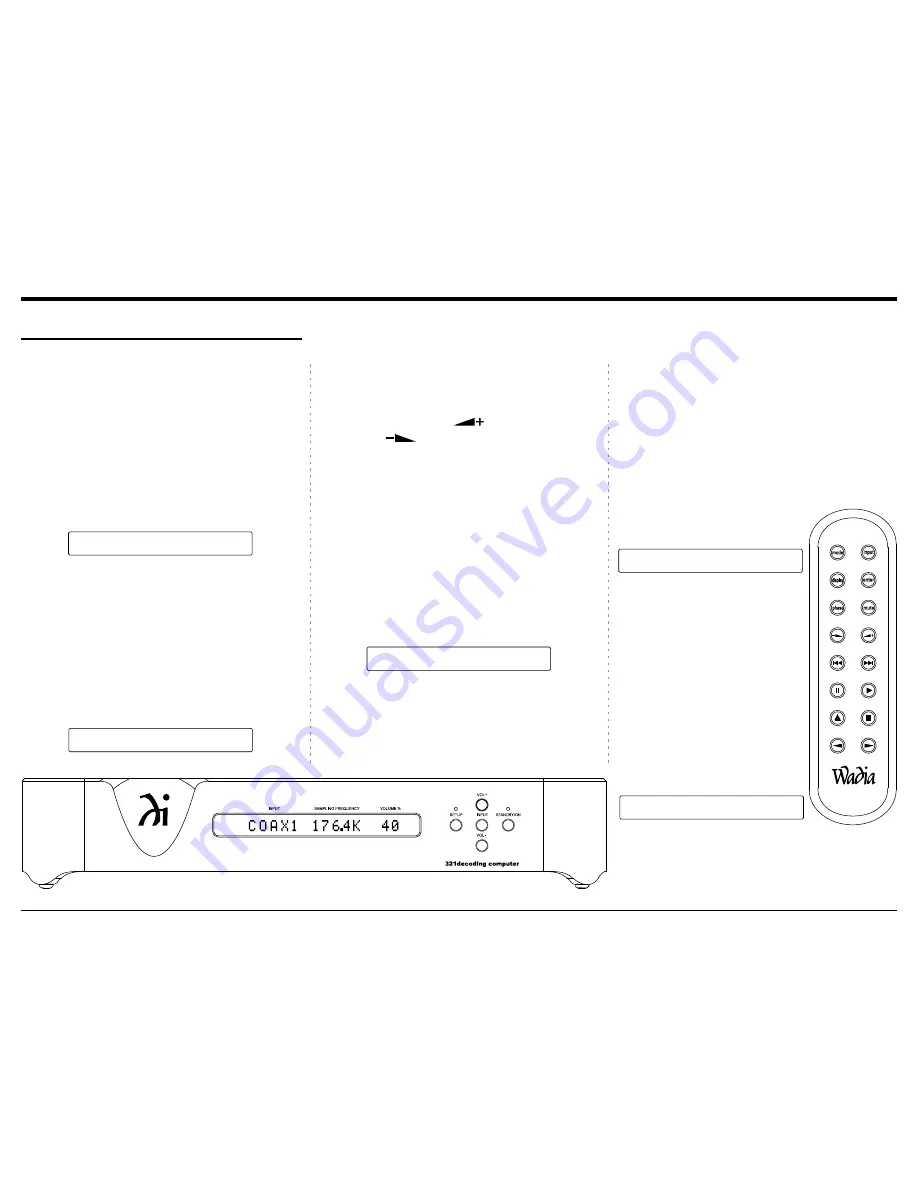
To change the Volume Level of the Wadia 321, press 

the Front Panel Push-button to increase the 

Volume or the VOLume - Push-button  to decrease the 

Volume. The Volume Level may also be changed by 

using the Remote Control           (Volume Up) Push-

button or the           (Volume Down) Push-button for 

the desired listening level. Refer to figures 53 and 56.

Note: A Volume Setting of 88% on the Wadia 321 will 

provide optimum performance when it is con

-

nected to a Preamplifier (Integrated Amplifier or 

Receiver).

Mute

Press the Remote Control MUTE Push-button to mute 

the Audio Outputs. Refer to figure 56. When the Wa-

dia 321 is muted, the Front Panel Display will display 

a series of dashes where the Volume % is normally 

displayed. Refer to figure 52. Pressing the MUTE 

Push-button a second time to un-mute the 321.

Display Brightness

The Front Panel Display Brightness may be changed 

from the default setting. The 321 will remember the 

Power On and Off

The Red LED above the STANDBY/ON Push-button 

lights to indicate the 321 is in Standby mode. To 

switch ON the 321, press the STANDBY/ON Push-

button on the Front Panel or the MODE (Power On) 

Push-button on the Remote Control. The 321 will go 

through a brief startup initialization with the Front 

Panel Display indicating the last used Input Source 

and Volume Level Setting. Refer to figures 50, 53, and 

56. To switch OFF the 321 press the STANDBY/ON 

Push-button on the Front Panel or the MODE (Power 

Off) Push-button on the Remote Control.

Source Selection

Press the INPUT Push-button on the Front Panel 

or the INPUT Push-button on the Remote Control 

to select the desired source. Refer to figures 53 and 

56. When the selected Input Source stops sending a 

Digital Audio signal to the Wadia 321, the Front Panel 

Display will display a series of dashes where the 

Sampling Frequency is normally displayed. Refer to  

figure 51.

How to Operate the 321

Figure 53

Figure 56

Figure 50

C O A X 1       1 9 2 K       7 5

VOLUME %

INPUT

SAMPLING FREQUENCY

Figure 54

C O A X 1       1 9 2 K       7 5  |

VOLUME %

INPUT

SAMPLING FREQUENCY

U S B         1 9 2 K       7 5

VOLUME %

INPUT

SAMPLING FREQUENCY

Figure 55

Figure 51

C O A X 1     - - - - -       7 5

VOLUME %

INPUT

SAMPLING FREQUENCY

C O A X 1       1 9 2 K     - - -

VOLUME %

INPUT

SAMPLING FREQUENCY

Figure 52

How to Operate the 321

Summary of Contents for 321

Page 1: ...Wadia Digital LLC 2 Chambers Street Binghamton New York 13903 2699 Phone 607 723 3539 Fax 607 724 0549 www wadia com 321decoding computer Owner s Manual ...

Page 2: ...e point where they exit from the apparatus 11 Only use attachments accessories specified by the manufacturer 12 Use only with the cart stand tripod bracket or table specified by the manufacturer or sold with the apparatus When a cart is used use caution when mov ing the cart apparatus combination to avoid injury from tip over 13 Unplug this apparatus during light ning storms or when unused for lon...

Page 3: ... the Remote Control Perform the following steps to remove the battery from the Remote Control 1 Press the tab and lift up on the Battery Cover and temporarily place it aside Refer to figures 2 and 3 2 Refering to figure 6 press on the bottom edge of the battery to release the battery from the molded battery socket Then remove the bat tery from inside of the Remote Control 2 Remove the CR2032 Batte...

Page 4: ...ided for you to record that information Serial Number ________________________________ Purchase Date ________________________________ Dealer Name _________________________________ Safety Instructions 2 Battery Installation and Replacement 3 Thank You and Please Take a Moment 4 Technical Assistance and Customer Service 4 Table of Contents 4 General Information 5 Connector and Cable Information 5 In...

Page 5: ...odulation Digital Signal present at the Coaxial Optical and USB Digital Inputs Other Digital Audio Signal Format Types will cause the Audio Outputs of the 321 to be muted 5 The term Absolute Phase relative to reproduction of sound by Loudspeakers or headphone refers to the phase of the reproduced signal relative to the original signal retaining the original polarity This applies regardless of the ...

Page 6: ...mic range and extremely low distortion for both Disc and external sources Balanced Outputs The Balanced Outputs allow the connection of long cable lengths without a loss in sound quality Precision Tracking Volume Control Volume levels are controlled by a Digitally Controlled Attenuator System Alphanumeric Fluorescent Display The Front Panel Information Display indicates the Source Selection Sampli...

Page 7: ...best location for your 321 There is additional information on the next page pertaining to installing the 321 into cabinets Side View of the 321 Front View of the 321 17 7 8 45 4cm 2 7 8 7 3cm 3 3 8 8 6cm 17 7 8 45 4cm 16 7 16 41 8cm Rear View of the 321 17 7 8 45 4cm 16 7 16 41 8cm ...

Page 8: ...ngest possible operating life for any electronic instrument Do not install the 321 directly above a heat generating device such as a Power Amplifier Allow at least 2 inches 5 1cm above the top 5 8 inches 1 6cm below the bottom and 1 inch 2 5cm on each side of the 321 so that airflow is not obstructed Allow 20 inches 50 8cm of depth for airflow and cable connections 321 Side View 20 50 8cm 321 Fron...

Page 9: ...S 2 and 1 for components with a Digital Audio Coaxial Output DIGITAL AUDIO INPUTS OPTICAL INPUTS 2 and 1 for components with a Digital Audio Optical Output USB DIGITAL AUDIO INPUT with control signal for connection to a computer UNBALANCED AUDIO OUTPUTS analog audio output signals to a Preamplifier or A V Control Center BALANCED AUDIO OUTPUTS analog audio output signals to a Preamplifier or A V Co...

Page 10: ...put Connection Balanced or Unbal anced may be used simultaneously Analog Audio Connections 1 Connect audio cables from the 321 UNBALanced AUDIO OUTPUTS R L Right and Left con nectors to the unbalanced Aux Input Connectors on the Preamplifier A V Control Center Integrat ed Amplifier or Receiver Note 1 The Balanced Outputs may be used instead of the Unbalanced Outputs Digital Audio Connections 2 Con...

Page 11: ...nnect balanced audio cables from the 321 AU DIO OUTPUTS Right and Left connectors to the balanced Input connectors on the Power Amplifier Note If two Power Amplifiers are used connect the unbalanced AUDIO OUTPUTS L R to the unbalanced Inputs on the second Amplifier Digital Audio Connections 2 Connect a Digital Optical Cable from the 321 DIGITAL AUDIO INPUTS OPTICAL 1 connector to the CD Player Dig...

Page 12: ...r Wadia Products Press the or to adjust the Volume Level Up or Down Steps thru the Digital Inputs 1 5 for source selection Press MODE to switch power On or Off to the 321 Mutes the audio Press DISPLAY to adjust brightness of the 321 Front Panel Display Press PHASE to change the phase of the Outputs Connections ...

Page 13: ...coding Front Panel DISPLAY indicates the Source Sam pling Frequency Volume Level Percentage Phase Operational Functions and Setup Mode Settings Front Panel Displays Controls Push buttons and Jack SETUP Push button with indicator activates the Setup Mode for changing operational settings Increases the Volume Level Decreases the Volume Level ...

Page 14: ... indicated on the Front Panel Display Refer to figure 2 3 Press the SETUP Push button until the LED above the SETUP Push button is extinguished How to Operate the Setup Mode The Default Settings Chart that follows indicates the Function Name Default Setting and the Page Number for additional information Default Settings Firmware Version Default Settings Function Name Setting Page No AUTO POWER OFF...

Page 15: ...er Mute Press the Remote Control MUTE Push button to mute the Audio Outputs Refer to figure 56 When the Wa dia 321 is muted the Front Panel Display will display a series of dashes where the Volume is normally displayed Refer to figure 52 Pressing the MUTE Push button a second time to un mute the 321 Display Brightness The Front Panel Display Brightness may be changed from the default setting The 3...

Page 16: ... Menu Folder Refer to figure 4 the computer and select the USB Drive with the Media Playback Program The 321 USB Input is compatible with PC Comput ers using Microsoft Windows Vista SP2 Win dows 7 SP1 and Windows 8 SP1 It is also com patible with Apple Macintosh Computers using OS 10 9 Mavericks or later When using a PC Computer with Windows a spe cial Wadia USB Audio Software Driver needs to be i...

Page 17: ...e 321 con t 2 Right mouse button click to bring up the menu and then select the Sound and Audio Refer to figures 14 and 15 3 Select the Speakers Wadia USB Audio and then click on the SET DEFAULT button Refer to figures 16 and 17 Notes 1 When the Wadia USB Audio Product is not connected to your computer the previous default Audio Device will be selected 2 If other Wadia Products with USB Audio Conn...

Page 18: ...Sampling Rate to the active Windows Playback Program Note In general when the original music is recorded at a higher Sampling Rate the result is usually more detail in the music However this higher rate results in consuming larger amounts of stor age space The Sample Rate usually should be set to match the Sample Rate of the music recording being played back ASIO HOSTS CAN CHANGE There are two cho...

Page 19: ...19 Photos ...

Page 20: ...20 ...

Page 21: ...21 Photos con t ...

Page 22: ...s 50 60Hz at 30 watts 230 Volts 50 60Hz at 30 watts 240 Volts 50 60Hz at 30 watts Standby Power less than 0 25 watts Note Refer to the rear panel of the 321 for the correct voltage Overall Dimensions Width is 17 7 8 inches 45 4cm Height is 3 3 8 inches 8 6cm including feet Depth is 20 inches 50 8cm including the Front Panel and Cables Weight 25 pounds 11 4 kg net 29 5 pounds 13 4 kg in ship ping c...

Page 23: ... damage Use the original shipping carton and interior parts only if they are all in good serviceable condition If a shipping carton or any of the interior part s are needed please call or write Customer Service Depart ment of Wadia Refer to page 4 Please see the Part List for the correct part numbers Quantity Part Number Description 1 034555 Shipping carton only 1 034556 Top foam pad 1 034554 Bott...

Page 24: ...nt of its products is the policy of Wadia Digital who reserve the right to improve design without notice Printed in the U S A Wadia Digital LLC 2 Chambers Street Binghamton NY 13903 www wadia com Wadia Digital Part No 04146801 ...

Reviews: