Infrarot
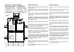
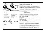
Empfangsteil
infrared
receiver
schwarz
black
rot
red
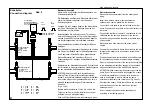
Steuerrelais
Zentralverriegelung
Control relay, central door
locking
2 poliger Stecker für
Zentralverriegelung
Two contacts connector
for central door locking
6 poliger Stecker
Six contacts connector
Abzweigverbinder
Snap-lock
connector
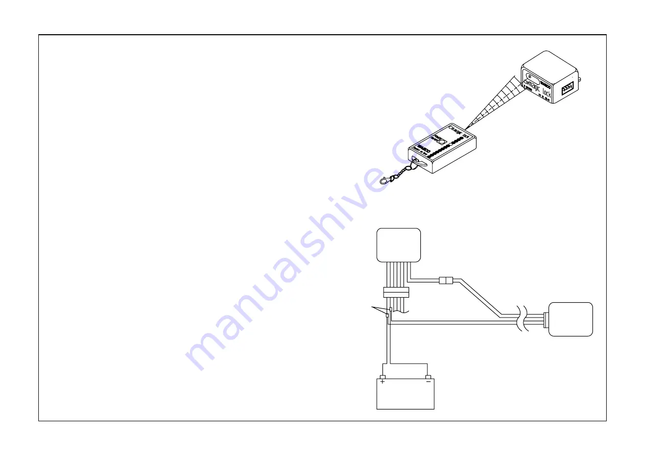
Abb. 3
Diagram 3
Abb. 4
Diagram 4
The control relay of the central locking has an electrical preparation which
enables easy connection of the infrared remote control.
Assembly instructions:
Localize the place of assembly of the control relay.
Connect the two contacts connector plugs of the infrared receiver to the free
two contacts connector plugs of the central locking control relay.
Connect the black and red wire of the connecting cable set with the black and
red connecting wire of the central locking control module (see also diagram 2).
For the connection use the 2 snap-lock connectors which are part of the
supplied set.
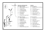
Fit the infrared receiver. In doing so do not forget that in order for the remote
control to function properly, visual contact must exist between the transmitter
and receiver. Suitable places for assembly are, for example:
1. Top side of the dashboard
2. Near the inside mirror.
Use the enclosed tapping screws or the Velcro tape for assembly purposes.
Connect the 4-pin plug with the infrared receiver.
Attention: Instructions for laying the cable. The connecting cable is not to be
crushed or to come into contact with mowing parts.
When laying the cable take care to ensure that these do not become damaged
as a result of using unsuitable tools.
Do not push the cable behind door seals: do not lay it behind firmly fixed
window seals (danger of broken glass).
If possible lay the cable behind original car panelling or underneath window
seals which are easy to raise.
Instruction for use:
In order for the remote control to operate perfectly, a visual contact is
necessary between transmitter and receiver.
When the distance to the receiver is less than approx. 4 m and after the
transmitter has been activated for approx. 1 sec. and has been directed
towards the receiver, it is possible to open and close the central locking system.
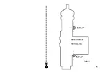
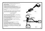
Please remember that - as it is a question of an infrared appliance - only signals
that get through to the front side of the receiver will be evaluated - see diagram
3 for more details.
9
Batterie
Battery
schwarz
black
rot
red


