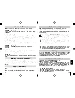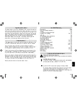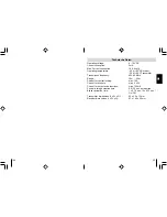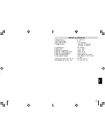
48
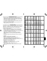
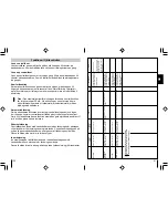
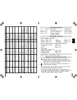
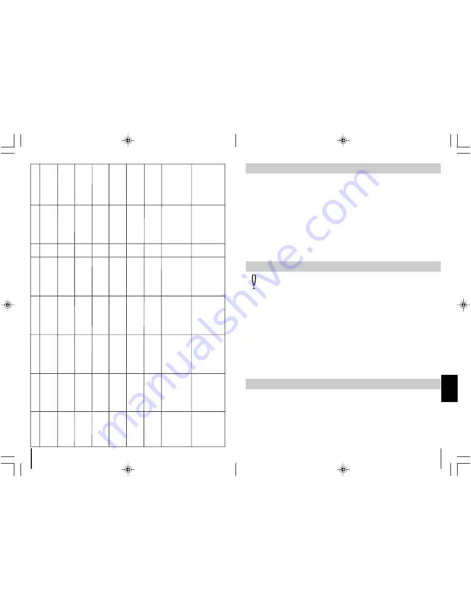
Right turn
signal
Unlock
Lock
Circuit
diagram
Doorswitch
Note
black/green / in the wiring
loom at the left entry
black/green / in the wiring
loom at the left entry
black/green / in the wiring
loom at the left entry
black/green / in the wiring
loom at the left entry
black/green / in the wiring
loom at the left entry
black/green / in the wiring
loom at the left entry
green/black / 30 way
white con-nector among
the dashboard
blue/brown / in the wiring
loom at the left entry
blue/brown / in the wiring
loom at the left entry
green/blue / at the left
A-pillar
green/blue / at the left
A-pillar
brown/grey / at the left
A-pillar.
brown/red or grey at the
left A-pillar
green/blue / at the left
A-pillar
brown/grey / at the left
A-pillar
yellow/blue / Pin 7 at the
control unit of the original
central locking
Pin 24 / 26 way white
connector at the control
unit of the original central
locking
Pin 17 / 26 way yellow
connector at the control
unit of the original central
locking
No. 6
No. 6
No. 4
No. 4
No. 6
No. 4
No. 4
No. 3
No. 3
brown/white / on the door
switchat the left side at the
A-pillar. The doorswitch is
switched negative.
brown/yellow / on the door
switch at the left side at the
A-pillar. The door switch is
switched negative
brown/yellow / on the door
switch at the left side at the
A-pillar. The door switch is
switched negative.
brown/white / on the door
switch at the left side at the
A-pillar. The door switch is
switched negative.
brown/white / on the door
switch at the left side at the
A-pillar. The door switch is
switched negative.
brown/white / on the door
switch at the left side at the
A-pillar. The door switch is
switched negative.
brown/yellow / on the door
switch at the left side at the
A-pillar. The door switch is
switched negative.
brown/grey/yellow / on the
door switch at the left side
at the B-pillar. The door
switch is switched
negative.
brown/grey/yellow / on the
Door switch at the left side
at the B-pillar.
The door switch is
switched negative.
Connect blue/yellow control
line to door - grey/red line
to ZV pump
Connect blue/yellow control
line to door - grey/red line
to ZV pump
Connect blue/yellow control
line to door - grey/red line
to ZV pump
The control unit of the
original central locking is
on the left side behind the
cover from the A-pillar
If necessary contact pins
of BMW with original part
number 61 131 393 704
will be needed. The control
unit of the original central
locking is behind the
glove compartment.
If necessary contact pins of
BMW with original part
number 61 131 393 704 will
be needed. The control unit
of the original central locking
is behind the glove
compartment.
green/blue / at the left A-
pillar
green/blue / at the left A-
pillar
brown/green / at the left
A-pillar
grey/black / at the left
A-pillar
green/blue / at the left A-
pillar
grey/white / at the left
A-pillar
green/blue / Pin 6 at the
control unit of the
original central locking
Pin 25 / 26 way white
connector at the control
unit of the original central
locking
Pin 4 / 26 way yellow
connector at the control
unit of the original central
locking
Left turn
signal
black/white / in the wiring
loom at the left entry
black/white / in the
wiring loom at the left
entry
black/white / in the
wiring loom at the left
entry
black/white / in the
wiring loom at the left
entry
black/white / in the
wiring loom at the left
entry
black/white / in the
wiring loom at the left
entry
green/blue / 30 way
white con-nector among
the dashboard
blue/green / in the
wiring loom at the left
entry
blue/green / in the wiring
loom at the left entry
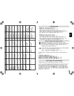
Audi 80 type 89 and
B4, year: 86-94
Audi 100 and A6
type C4, year: 90-97
without alarm
system
Audi 100, A6 type
C4, year: 90 - 97 with
alarm system
Audi A3 type 8L,
year : 96-00
Audi A4 type B5,
year: 94- without
alarm system
Audi A4 Typ B5
year: 94 - with alarm
system
BMW 3er E30, year:
82-90
BMW 3er E36, year:
91-
BMW 3er E36, year:
91-
153
S
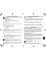
Obs!
För att undvika risk för kortslutning ska du alltid ta av
anslutningen från batteriets minuspol innan du börjar att arbeta med
fordonselektroniken. Om fordonet har ett extrabatteri måste även
denna minuspol kopplas ifrån.
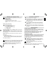
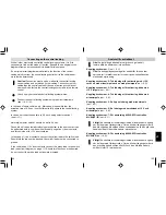
Anslut mottagaren med ledning av bifogat anslutningsschema
(se
✎
J
➀
), kontaktbeläggningsschema (se
✎
J
➁
) och
kopplingsschema (se
✎
J
➂
+
➃
).
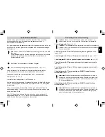
Vid anslutning till körriktningsvisarna (blinkers) tänds dessa 1 eller 2
gånger (om tillåtet enligt lag).
Beläggningsschema
(se
✎
J
➀
)
Kontaktbeläggningsschema
(se
✎
J
➁
)
Kopplingsschema dörrkontakt (-), kopplad till minus
(se
✎
J
➂
)
Kopplingsschema dörrkontakt (+), kopplad till plus
(se
✎
J
➃
)
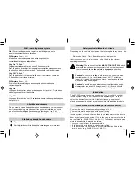
Ansluta mottagaren elektriskt
– Exempel 3:
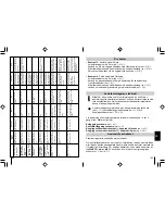
Ansluta kabel till jord
Avisolera kabeln med 5 mm (se
✎
H
➀
).
Använd en Ø 6 mm taggad kabelsko med klämanslutning (se
✎
H
➁
).
Kläm fast kabelskon på kabeländen med en kabelskotång (se
✎
H
➂
).
Skruva fast kabelskon vid en original-jordpunkt (se
✎
H
➃
).
– Exempel 4:
Förse kabel med flathylsa
Avisolera kabeln med 5 mm (se
✎
I
➀
).
Använd en passande kabelsko med abslutning för kabelskotång
(t ex flatstifthylsa) (se
✎
I
➁
).
Kläm fast kabelskon på kabeländen med en kabelskotång (se
✎
I
➂
).
Använd om nödvändigt anslutning med isolerat skaft (se
✎
I
➃
).
Dra kablar
Praktiskt taget alla centrallås styrs elektriskt.
Om centrallåset saknar en servomotor i förardörren (dörren kan inte låsas
eller låsas upp från passagerardörren) måste en sådan motor monteras in
i förardörren i efterhand. För detta ändamål kan en enstaka servmotor av
typ
WAECO, art.-nr. ML-11
användas. Anslut motorn enligt kopplings-
schemat nr. 1 (se
✎
K
➀
).
Ansluta till centrallåset


