Safety and installation instructions
Caution! Disposal instruction:
The product and its components contain a variety of recyclable materials as
well as environmentally damaging substances. Therefore, do not throw these
parts when they are defective or need replacement into the domestic waste.
Please take care in your own interest and for the sake of the environment that
such components are only disposed of in a proper and admissible manner.
Warning!
Inadequate cable connections can lead to short-circuits which cause
the following:
–
cable fires
–
triggering of the airbag
–
damage to electronic control equipment
–
failure of electrical functions (blinkers, brake-lights, horn, ignition, lights).
The following indications must be therefore considered:
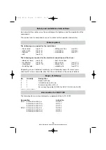
When working on the cabling of the vehicle, the following terminal designations
apply:
30
(input from battery plus direct),
15
(switched plus, behind battery)
31
(return cable from battery, GND)
58
(parking light)
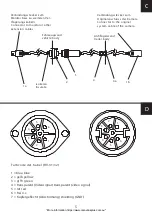
The securest form of connection is obtained by
soldering
the cable ends and then
insulating
the connection.
For detachable connections, only insulated cable lugs, connector plugs, and flat pin
bushings must be used. Do not use luster connectors.
Use crimp pliers for connecting the cables with cable lugs, plugs or flat pin bushings.
With cable connections to 31 (ground/GND):
Screw the cable with cable lug and toothed lock washer to a vehicle-specific
ground/GND bolt or screw it with a cable lug, sheet-metal screw and toothed lock was-
her to the car’s bodywork.
Always ensure proper connection to ground/GND!
Warning!
The components of this device which are inside the vehicle must be
securely fixed so that they cannot come loose and injure the vehicle’s occu-
pants under any circumstances (sudden braking, traffic accident).
14
428-03 RV-31 32.qxd 11/09/03 14:57 Page 14
“More information https://www.caravansplus.com.au"


