background image

Safety and installation instructions

Do not pull at the cables since this could impair the tightness and the operability of the
components.

The product and its components are not suitable for the operation under water.
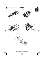
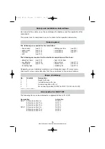
Tools required

The following are required for the installation:

– Scale (ruler)

(see B 1)

– drilling machine

(see B 5)

– prick punch

(see B 2)

– screwdriver

(see B 6)

– hammer

(see B 3)

– screwdriver

(see B 7)

– drill

(see B 4)

The following are required for the electrical connection and the check:

– diode test lamp

(see B 8) 

– heat shrink hose

– or voltmeter

(see B 9)

– hot-air drier

(see B 11)

– crimp pliers

(see B 10)

– hatchet iron

(see B 12)

– insulating tape

– soldering tin

(see B 13)

Depending on your individual assembly, you will probably need still more screws, 
sheet-metal screws and cable-clips than those contained in the scope of delivery.
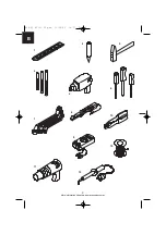
Scope of delivery

No.

Quantity Designation

1

1

Socket with cap

2

1

Installation box with cap

3

1

Screw connection with nut

4

1

5m connecting cable (RV-405 for RV-31; RV-505 for RV-32)

Subject to technical changes!

Accessories for RV-31/32

The following items can be delivered as supplementation to RV-31/32:

Designation

Article No.

RV-31

Extension cable, 5 m

RV-405

Extension cable, 10 m

RV-410

Extension cable, 15 m

RV-415

RV-32

Extension cable, 5 m

RV-505

Extension cable, 10 m

RV-510

Extension cable, 15 m

RV-515

16

428-03 RV-31 32.qxd  11/09/03  14:57  Page 16

“More information https://www.caravansplus.com.au"

Summary of Contents for MOBITRONIC RV-31

Page 1: ...r Anh ngerbetrieb Montage und Bedienungsanleitung GB 13 Plug connection for the trailer operation Installation and Operating Manual titelseite_neu_a5 fm Seite 1 Freitag 14 Januar 2005 10 37 10 More i...

Page 2: ...3 1 2 3 4 5 A a b c 428 03 RV 31 32 qxd 11 09 03 14 57 Page 3 More information https www caravansplus com au...

Page 3: ...4 1 2 3 4 5 6 7 8 10 9 11 12 13 B 428 03 RV 31 32 qxd 11 09 03 14 57 Page 4 More information https www caravansplus com au...

Page 4: ...he original system cable of the camera C D 5 6 1 2 3 4 2 1 1a 2 4 3 4a 1b 6 5 4 3 isolieren Insulate Fahrzeugwand vehicle body Anh ngerwand trailer body Farbcode der K abel R V 31 32 1 blau blue 2 gel...

Page 5: ...ning may result in damage to materials and may impair the functioning of the product The rhombus indicates installation steps which have to be carried out To ensure problem free fitting read these ins...

Page 6: ...30 input from battery plus direct 15 switched plus behind battery 31 return cable from battery GND 58 parking light The securest form of connection is obtained by soldering the cable ends and then ins...

Page 7: ...nelling are to be fastened in such a way that they cannot become loose and damage other parts and lines and impair vehicle functions steering pedals etc Do not mount any components within the head imp...

Page 8: ...see B 12 insulating tape soldering tin see B 13 Depending on your individual assembly you will probably need still more screws sheet metal screws and cable clips than those contained in the scope of...

Page 9: ...le drilled beforehand with the cap nut showing outward and bolt it with the lock nut see C 4a Lay the connecting cable to determine the length up to the installation socket see C 2 Cut the cable with...

Page 10: ...r lunda G teborg Fon 46 31 7341100 Fax 46 31 7341101 E Mail info waeco se WAECO UK Ltd Dorset DT2 8LY Unit G Roman Hill Business Park UK Broadmayne Fon 44 1305 854000 Fax 44 1305 854288 E Mail sales w...

Reviews: