ProLine
™
�5���W�Power�Inverter�by�Wagan�Tech
®
www.wagan.com
5
©�����Wagan�Corporation.�All�Rights�Reserved.
Wagan�Tech�and�
wagan.com
�are�trademarks�used�by�Wagan�Corporation.
User’s�Manual—Read�before�using�this�equipment
6
REMOTE�ON/OFF�SWITCH�CONNECTION
A�supplied�cable�and�Remote�Switch�assembly�provides�a�convenient�remote�On/Off�
feature.
POWER INVERTER OUTPUT WAVEFORM
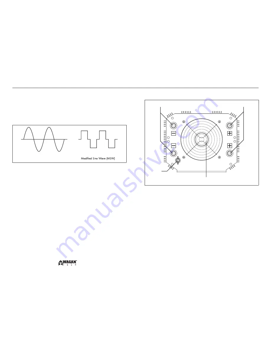
This�inverter’s�AC�output�is�a�modified�sine�wave�(MSW)���5�volts�AC.�The�
comparison�of�modified�sine�wave�and�household�AC�is�shown�in�the�figure�below.
Sine�Wave
This�modified�sine�wave�has�a�root�mean�square�(RMS)�voltage�of���5�volts.�Most�
ordinary�AC�voltmeters�are�calibrated�to�read�“average”�voltage�and�assume�that�
the�AC�waveform�will�be�a�pure�sine�wave.�These�meters�will�not�correctly�read�
MSW�voltage,�and�will�display�about����to�3��volts�too�low.�Any�multi-meter�
identified�as�“TRUE�RMS”�will�accurately�read�MSW�correctly.
INVERTER OUTPUT CHARACTERISTICS
The�high�output�terminals�and�outlets�of�this�inverter�are�wired�in�a�similar�manner�
to�that�of�house-hold�wiring.�The�“ground”�connection�(the�round�connection�on�an�
outlet)�is�connected�to�inverter�frame’s�ground.�The�two�“blade”�connections�on�an�
outlet�are�labeled�LIVE�and�NEUTRAL�because�the�neutral�is�connected�to�ground�
as�in�standard�household�distribution�wiring.�This�output�conforms�to�the�National�
Electric�Code�(NEC).
REAR PANEL
High-Speed�
Cooling�Fan
��Negative�(−)�DC�
Input�Terminals
��Positive�(+)�DC�Input�
Terminals
Ground�
Terminal
HIGH-SPEED�COOLING�FAN
Fan�automatically�operates�when�there�is�power�and�switch�is�turned�on.�
NEGATIVE�DC�(−)�INPUT�AND�POSITIVE�DC�(+)�INPUT�TERMINALS
Both�negative�terminals�are�wired�together�inside�the�inverter.�Similarly,�both�positive�
terminals�are�wired�together�inside�the�inverter.�For�AC�loads�up�to��5���watts�only�
one�positive�and�one�negative�cable�set�is�required.�For�AC�loads�from��5���to�
5����watts�use�two�sets�of�cables.
After�DC�cables�are�installed,�both�sets�of�DC�terminals�should�be�insulated�to�
protect�from�accidental�short�circuits.
GROUND�TERMINAL
This�terminal�is�for�attaching�a�6�gauge�insulated�safety�ground�wire.�This�safety�
wire�protects�personnel�if�there�is�an�unlikely�failure�in�either�the�cabling�or�
enclosure�insulation.�Do�not�directly�connect�this�ground�to�any�negative�DC�terminal�
on�the�inverter.�This�safety�wire�is�to�be�connected�to�the�vehicle�frame�or�earth�
ground�or�negative�battery�terminal�as�described�in�the�installation�procedure.


