ProLine
™
�5���W�Power�Inverter�by�Wagan�Tech
®
www.wagan.com
9
©�����Wagan�Corporation.�All�Rights�Reserved.
Wagan�Tech�and�
wagan.com
�are�trademarks�used�by�Wagan�Corporation.
User’s�Manual—Read�before�using�this�equipment
10
yields�only�3�%�of�the�battery�capacity.�The�installer�must�carefully�plan�the�capacity�
of�battery�bank�or�the�run�time�may�be�seriously�affected.�To�the�inexperienced�
installer,�several�trial�battery�capacities�may�be�required�to�make�sure�a�large�
enough�battery�capacity�is�available�to�achieve�the�desired�run�time.
���
9�
8�
7�
6�
5�
4�
3�
��
��
�
�
�8� ���
�� 4� 6� 8� ��� ��� �4� �6�
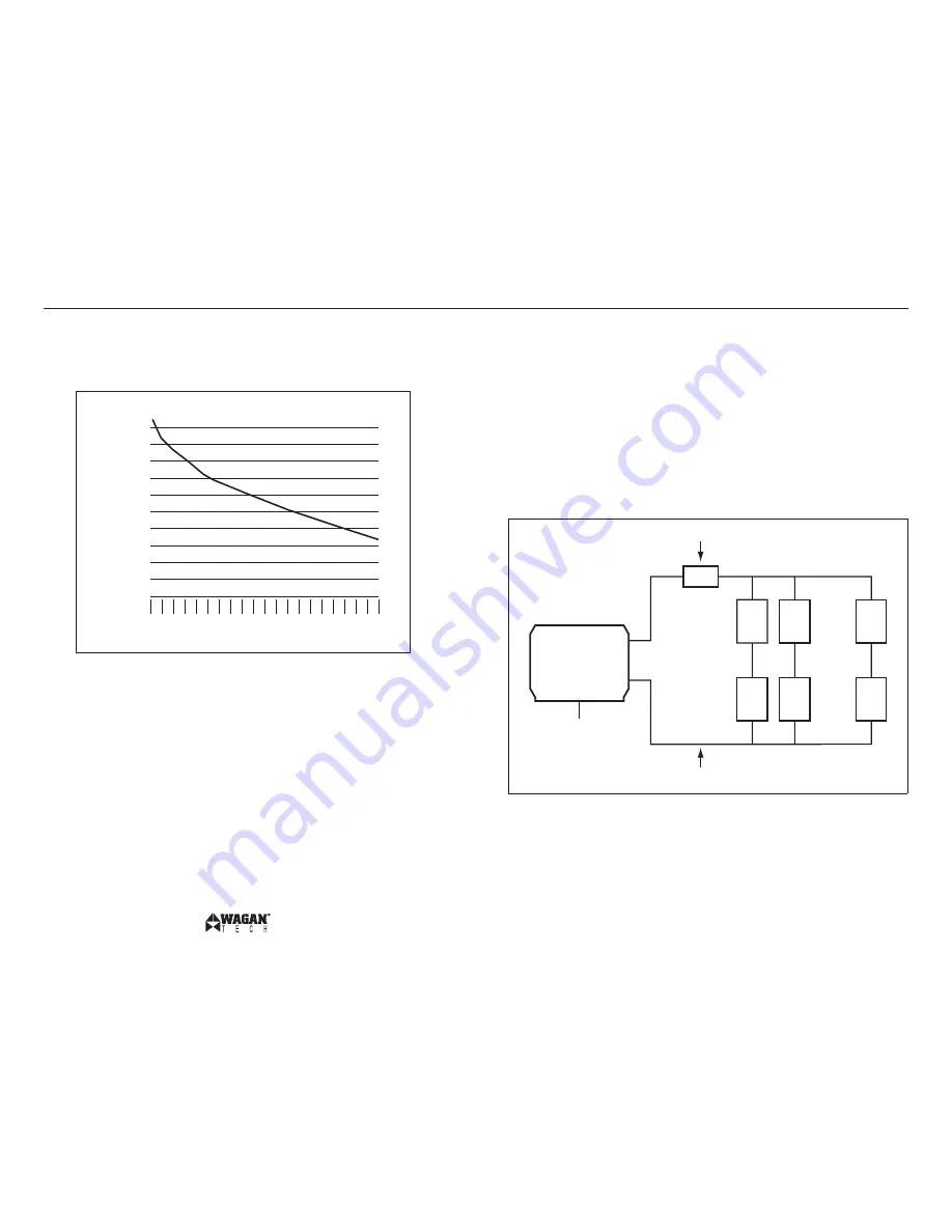
The�curve�can�be�applied�to�any�lead�acid�battery�under�load�providing�that�it�has�
an�AH�rating�at�the����hour�rate.
Continuing�with�the�previous�example,�the��5��amp�load�will�need�to�run�for����
hours,�so�we�begin�configuration�with�a��,5���AH�battery.�If�the�vertical�is��,5���
and�the�horizontal�is��5��amps,�the�percentage�of�load�on�the�battery�is���%.�The�
curve�shows�that�the��,5���AH�is�derated�to�9�%�of�maximum.�This�means�that�the�
battery�will�have�to�be��6,5���AH�for�the�full����hour�run�time.�It�is�important�to�
add�some�extra�battery�capacity,�because�as�the�batteries�age�they�will�lose�AH�
capacity.
CONFIGURATING THE BATTERY BANK
Six�volt,�����AH�“golf�cart”�batteries�were�selected�for�these�illustrations�because�
they�are�generally�readily�available�and�relatively�inexpensive.�They�are�deep-cycle�
type�and�with�regular�recharging�they�have�a�relatively�long�life.�These�batteries�
are�“flooded”�type;�they�freely�vent�hydrogen�and�oxygen�while�under�charging�
and�heavy�discharge.�They�must�be�vented�to�outside�air�to�prevent�accumulation�of�
explosive�gases.
FUSING�REQUIREMENTS
NOTE:��It�is�important�that�for�this�5����watt�inverter�has�two�ANL�4���ampere�or�
equivalent�main�battery�fuses�be�added�to�the�positive�(+)�battery�cable�as�close�
as�possible�to�the�battery�bank’s�positive�terminal.�The�fuse�amperage�rating�must�
be�sized�to�allow�simultaneous�operation�of�all�the�AC�appliances�to�be�powered,�
allowing�for�the�momentary�high�startup�current�requirements�of�inductive�loads.�Use�
the�recommended�fuse�block�(fuse�holder)�and�fuse,�or�an�electrical�equivalent.�ANL�
type�fuses�and�fuse�holders�are�readily�available�from�marine�supply�dealers.
The�fuses�are�very�important�to�protect�equipment,�batteries�and�personnel.�The�fuses�protect�
against�battery�explosion�if�the�cables�that�connect�to�the�inverter�accidentally�short.��
BATTERY�BANK�DIAGRAM
The�diagram�below�shows�inverter�connections�to�a�battery�bank�with�recommended�
fuse�protection.
INVERTER
Safety�Ground
–
+
��to�4�cables�and�fuses
��to�4�cables
6V
���AH
6V
���AH
6V
���AH
6V
���AH
6V
���AH
6V
���AH
+
–
+
–
+
–
+
–
+
–
+
–
Fuse
WARNING: EXPLODING BATTERIES CAN SPRAY MOLTEN LEAD, HOT SULFURIC
ACID AND PLASTIC FRAGMENTS. BATTERIES THAT ARE CHARGING OR UNDER
HIGH DISCHARGE RATES CAN PRODUCE EXPLOSIVE HYDROGEN GAS INTO THE
SURROUNDING AREA. BE SAFE—FUSE THE BATTERY BANK AND MAKE SURE THE
BATTERY BANK LOCATION IS PROPERLY VENTILATED.


