Slimline
™
Power Inverters by Wagan Tech
®
5
www.wagan.com
REAR PANEL
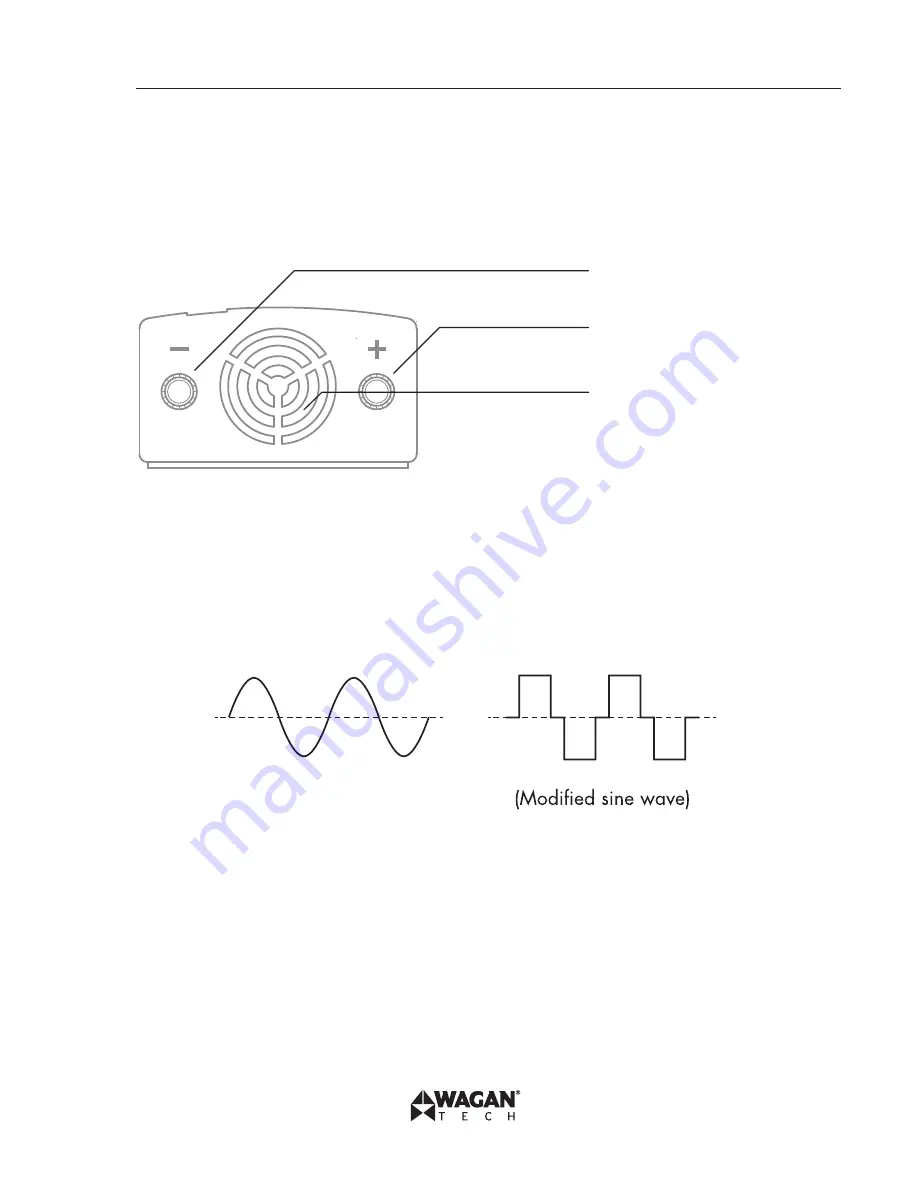
All inverters described in this manual have two terminals for connecting battery cables. One
terminal is the Positive (+) terminal [red]; the other is the Negative (−) terminal [black]. The
Positive battery cable should have a Battery Protection Fuse installed within one foot of the
battery connection. The negative cable can be directly attached to the negative battery terminal.
In some cases, a metal vehicle frame can be used as part of the negative cable to the battery.
Cooling Fan (internal)
Positive Terminal (red)
Negative Terminal (black)
High Speed Fan – The fan turns on when there is a high load or an elevated temperature to keep
the inverter cool. Do not block. Keep 2-inch clearance.
MEASURING THE AC VOLTAGE
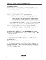
This inverter’s AC output is a modified sine wave (MSW) 115 volts AC. Your household AC
output is pure sine wave. The comparison of modified sine wave and household AC is shown in
the figure below.
(Pure sine wave)
This modified sine wave has a root mean square (RMS) voltage of 115 volts. Most ordinary AC
voltmeters are calibrated to read “average” voltage and assume that the AC waveform will be a
pure sine wave. These meters will not correctly read MSW voltage, and will display about 20 to
30 volts too low. Any multi-meter identified as “TRUE RMS” will accurately read MSW correctly.


