10
EN-RATIOfresh-250-400_TI-MA-0809-11214900
3.6 Installing the Primary Circuit (fig. 7)
In order for the RATIOfresh freshwater station to yield the
desired output, it must be supplied with a sufficient volume
of hot water either from a buffer storage tank or a district
heating system. Table 14 lists the required primary flow
temperatures.
The primary circuit may never be serviced by another
pump even only temporarily!
●
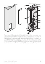
Route primary flow line
(1)
from the hot storage tank sec-
tion to the RATIOfresh-freshwater station and connect
with soldered or threaded connection sets. At the RATIO
cylinder use 18-1½" connection sets with swivel nut
(4)
,
soldered or threaded connection
(3)
and flat seal
(2)
,
and connection sets 22-1¼" with swivel nut
(7)
, soldered
or threaded connection
(6)
and flat seal
(5)
at the station.
Install a bleeder if lines in the primary flow are installed in
an upward direction!
●
Connect the primary return line
(8)
and route to the cor-
responding storage tank connection that matches the
temperature level. Table 14 lists the return temperatures
of the station in dependency of the operating condi-
tions.
●
Route cable of the temperature sensor
(9)
marked
“T
prim
” from the freshwater station along the primary flow
and attach sensor in the aux. heating section of the
buffer cylinder approx. 10 cm below the actual tapping
point of the primary flow. Use the uppermost position of
the connector block
(10)
at the RATIO buffer cylinder.
The sensor must correctly detect the cylinder temperature.
Check the correct position of the sensors after the initial
startup!
Wa
gner
&
Co
10 cm
7
6
5
9
4
3
2
5
6
7
8
9
10
4
1
3
2
10
Figure 7 Primary circuit installation
6-1
Primary flow line;
6-2
Flat seal;
6-3
Soldered or threaded connection;
6-4
Swivel nut;
6-5
Flat seal;
6-6
Soldered or threaded union;
6-7
Swivel
nut;
6-8
Primary return line;
6-9
Temperature sensor T
buffer
;
6-10
Connector block.


