background image

EN-RATIOfresh-250-400_TI-MA-0809-11214900

17

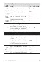
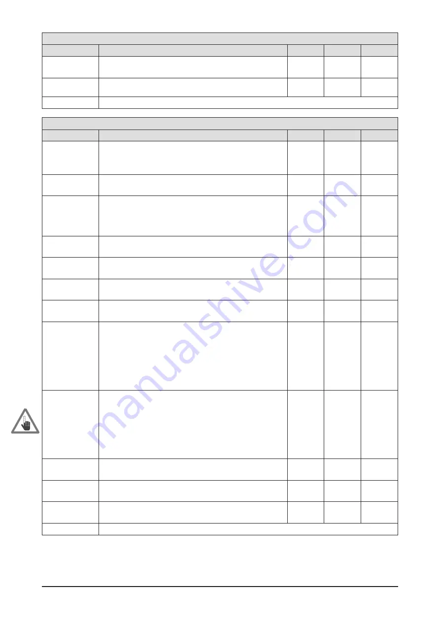
Table 10 Value Level – SETTINGS: TIME

Designation

Description

Range

Base value

Your value

WEEKDAY

[Monday]

Make sure the day of the week and the time are set correctly especially
when using the circulation and disinfection function.

Monday to
Sunday

-

TIME
[00:00]

Make sure the day of the week and the time are set correctly especially
when using the circulation and disinfection function.

00:00 –
24:00

-

END

Select this menu item with the < and > keys and press the

key to return to the menu level.

Table 11 Value Level – SETTINGS: SERVICE

Designation

Description

Range

Base value

Your value

CODE NUMBER
800174

MON-005

This menu serves to change control parameters with special
applications and requires input of a code to prevent accidentally
changing these parameters. The code is available upon request. Use
the < and > keys to set the correct code.

0 – 255

RS232-INTERVAL

[003] s

Setting the output interval of the serial interface.

1 – 255 s

3 s

PRIMARY FACTOR

[20]

Compensation factor to affect the sensitivity of the hot water control in
dependency of the buffer cylinder temperature. If the compensation
factor is set to 0, compensation is not active and that also applies to
when neither primary flow sensor nor buffer cylinder sensor are
connected.

0 – 240

20

Kp CIRCULATION

[05] K

Boost factor of pump in relation to the determined temperature
difference hot water-circulation return

1 – 10 K

5 K

IMPULSE/LITRE

[35 ]

Impulse value of the volume flow sensor

0 – 100

35

Kp VOL

[05] K

Boost factor of pump in relation to drawn water volume.

1 - 50 K

5 K

RATIOfresh type

[250-400]

Controlling variation - this selection resets all values to factory setting.

250/400/
800

250/400

ADAPTATION
VALUES

Start values for calculation of pump power. For all 10 tapping slots start
values are set. They are the base of calculating the required pump
force. The actual temperatures and tapping volumes are incorporated
in the calculation. The individual values can be examined and changed
by selecting the respective sub-menus. If not all slots are reached
during controlled tapping while commissioning the system (chap. 5.6),
the adaptation values can be set directly. The power of the pump
continuously increases over the ten tapping slots. Each slot must have a
higher value than the previous one.

ADAPT. VALUE 1

60 °C 01 [08]

Adaption value of the first tapping slot. On the left the current hot water
temperature is shown. In the centre you can see the tapping slot
currently in use. On the right, the momentary adaptation value can be
seen. In order to make an adjustment, the adaptation value (display:
top) related to the current tapping slot (display: centre) should be
selected. Increasing this value will also increase the initial pump power
of the slot. Setting the value to high results in risk of scalding, since the
controller only starts with the adaptation after 10 s and then reduces the
pump power until the set water temperature is reached.

5 – 90

8

ADAPT. VALUE 2

60 °C 02 [15]

Adaptation value of the second tapping slot

5 – 90

15

ADAPT. VALUE 10

60 °C 10 [71]

Adaptation value of the tenth tapping slot

5 – 90

71

PUMP INTERVAL

[200] ms

200 – 600
ms

200 ms

END

Select this menu item with the < and > keys and press the

key to return to the menu level.

Summary of Contents for RATIOfresh 250

Page 1: ...ely asdelivered Numerous Application Options The freshwater station can be combined with almost any heat source Oil gas wood logs and pellet boilers are as suitable as a solar installation or local or district heating dis tribution systems All it takes is a buffer cylinder whose ther mal stratification is supported by minimal return tempera tures within the primary circuit Protection from Legionel...

Page 2: ... C 5 25 K Pressure loss Dp secondary 370 mbar with 25 l min Voltage supply 230 V 50 Hz Fuses Operating voltage 230 V control fuse 100 mAT 250 V power fuse 2 AT 250 V To replace internal fuses de energize the device remove the screws on the controller and lift off cover fig 8 9 10 Dimensions of housing H x W x D 940 x 350 x 181 mm Color powder coated Upper section RAL 7035 light gray Bottom section...

Page 3: ...ping capacity 10 C 45 C sec 10 C 60 C sec 40 l min 98 kW 139 kW Coefficient of performance NL 10 C 45 C sec 82 C prim acc to DIN 4708 T3 10 C 60 C sec 85 C prim 10 C 60 C sec 75 C prim NL 19 5 NL 17 NL 11 Nominal hot water temperature 25 70 C Circulation return 5 70 C 5 25 K Pressure loss Dp secondary 490 mbar with 40 l min Voltage supply 230 V 50 Hz Fuses Operating voltage 230 V control fuse 100 ...

Page 4: ...n 1 Controller 2 Heat ex changer 85 57 80 ø 55 ø 55 181 350 80 7 Hot water 6 Cold water 9 Single jet meter 3 Circulation pump 10 Housing 8 Circulation Frontal view Top bottom view Drill pattern 64 32 254 521 827 70 Figure 2 RATIOfresh freshwater station viewed sectionally with dimensions and drilling template ...

Page 5: ...f valve 5 Primary return connection T 1 OT flat sealing made from brass with pump shut off slider incl backflow preventer 6 Cold water supply connection T1 OT flat sealing made from brass 7 Hot water outlet connection T 1 OT flat sealing made from brass 8 Circulation return connection option T IT closed with plug 9 Single jet meter brass chrome plated connections OT flat sealing QN 2 5 m h 10 Bott...

Page 6: ... protection function can be used to disinfect the entire hot water and circulation piping network thermally and during freely selectable times day or week program You choose between once per week Mon Sun or daily This function serves to pre vent the formation of bacteria and viruses in the potable water network The station uses an external relay output to activate the buffer storage auxiliary or b...

Page 7: ...t be checked regularly in accordance with DIN 4753 Theexhaust vent maynever be closed or restricted A corresponding water filter meeting current technology standards isto be installed intothecold water supplyline Connecting the Circulation The freshwater station RATIOfresh is designed to be con nected to a circulation line The circulation pump must be a commercially available stepped wet pump E pu...

Page 8: ...nsert in cluded plugs 2 Insert screws 3 to a distance of 1 cm and insert housing 4 into keyholes 5 and attach screws Tighten screws 3 firmly 3 3 Storage Tank Mounting fig 5 The RATIOfresh freshwater station is suitable for mounting directly on all buffer cylinders RATIO H series using the additionally available tank expansion kit cf accessories table 4 Remove the insulation of the RATIO H 1 cylind...

Page 9: ... 10 into the cold and hot water lines in close proximity to the station After irrigation cock 10 in the hot water line an addi tionalshut off cock 11 isneeded forflushingthepipes 3 5 Connecting Circulation Optional fig 6 DVGW 551 specifies a circulation element or system in larger hot water networks The circulation return 21 must be installed directly before tapping point 22 The circula tion pump ...

Page 10: ...maryflow are installed in an upward direction Connect the primary return line 8 and route to the cor responding storage tank connection that matches the temperature level Table 14 lists the return temperatures of the station in dependency of the operating condi tions Route cable of the temperature sensor 9 marked Tprim from the freshwater station along the primaryflow and attach sensor in the aux ...

Page 11: ...same way and plug into socket 7 required cable cross section 3 x 0 75 to 1 5 A fourth temperature sensor type KTY cf accessories can be connected via plug 8 and socket 9 A RS 232 interface cable available as an accessory can be connected to plug 12 socket 13 It is also possi ble to log all measured values the current controller sta tus and the current pump output This requires connect ing the 9 pi...

Page 12: ... P1 PE L N P2 PE L N Low voltage area 230 V 5V 15V R T 10 9 11 3 13 9 19 15 5 21 7 16 17 14 18 8 10 12 6 20 4 at rest 11 12 13 activated 11 12 13 Hot cold water sensors Hot water sensor blue Mass brown Circulation cold water sensor blue Primary circuit sensors Buffer cyl sensor blue Mass brown Primary flow sensor blue Optional data cable Plus 5V yellow TxData white RxData green Mass brown Optional...

Page 13: ... temperature level Use keys 6 and 8 to browse within the info level anddepict allcurrent temperatures andpumpoutputs 4 2 Controller Settings fig 10 Use key 7 to switch from the info level to the menu level Use keys and to select the desired setting menu Press key to switch to the value level where the set nominal values are listed in square brackets Select the desired menu item with the and keys a...

Page 14: ...nday Sunday 00 00 to 24 00 Table 6 Menu Level use the and keys to select the desired menu and confirm with the key Menu Description SETTINGS HOT WATER Settings for the primary circuit pump nominal hot water temperature and standby temperature details in Table 7 SETTINGS CIRCULATION Settings for the circuit pump operating mode determining the time frame for the circulation operating circulation ret...

Page 15: ...ange here 0 l min to 20 l min is divided by the control into 10 time slots and an internal control value is adjusted for each time window during the adaptation process Selecting an unfavorable max tap volume value can thus adversely affect the control performance The actual max output of the station is not reduced by this setting 20 to 80 l min 20 l min END Use the and keys to select and then conf...

Page 16: ...sk of scalding during the disinfection cycle MODE Nominal OFF Select operating mode for the disinfection of the hot water system When in automatic mode AUTO the hot water and circulation network are thermally disinfected at the selected time Select a time outside of the typical tapping times to reduce the risk of scalding With the operating mode ON the disinfection is activated continuously e g fo...

Page 17: ... of pump in relation to drawn water volume 1 50 K 5 K RATIOfresh type 250 400 Controlling variation this selection resets all values to factory setting 250 400 800 250 400 ADAPTATION VALUES Start values for calculation of pump power For all 10 tapping slots start values are set They are the base of calculating the required pump force The actual temperatures and tapping volumes are incorporated in ...

Page 18: ...used for the manual operation of the pump OFF ON AUTO AUTO BOILER REQUEST AUTO Software can be used to set the operating mode of the potential free relay and is used for manual operation OFF ON AUTO AUTO END Select this menu item with the and keys and press the key to return to the menu level Table 13 Value Level SETTINGS LANGUAGE Designation Description Range Base value Your value LANGUAGE Englis...

Page 19: ...for the specific on site condi tions fig 10 provides an overview over the menu structure and explains the use of the control keys Enter the corre sponding values into the setting menus in the following order HOT WATER CIRCULATION DISINFECTION SERVICE LANGUAGE and TIME Tables 7 to 13 pro vide assistance with selecting the respective values To finish enter the individual configuration into the Your ...

Page 20: ...t tapping volumes a controlled tapping should be per formed when initially starting up the system Please follow these steps and adhere to the described sequence of these steps 1 First select the menu item Tapping Area in the info level of the controller 2 Open a hot water tap until the display depicts 02 3 After approx 30 seconds the controller starts to adjust the hot water temperature to the des...

Page 21: ...ature in primary circuit 6 Pressure loss in primary circuit 7 Output level of the primary circuit pump For RATIOfresh 250 at nominal hot water temperature of 45 C 10 65 50 13 0 23 98 min 60 8 1 16 65 min 15 140 50 21 9 26 241 med 60 12 8 18 96 min 25 370 60 23 4 22 199 med 70 17 3 18 157 min For RATIOfresh 250 at nominal hot water temperature of 60 C 10 65 65 14 5 30 117 min 75 9 4 21 27 min 15 14...

Page 22: ...o 5 in the primary circuit flow and pump slider fig 11 no 7 to block primary cir cuit fig 11 no 2 9 Empty heat exchanger fig 11 no 3 on the primaryside by loosening the 1 bolt fig 11 no 6 at the primary flow connection and fig 11 no 10 at the primary re turn To remove the heat exchanger remove all four 1 swivel nuts fig 11 no 4 6 10 11 using a size 36 wrench Place heat exchanger over night into a ...

Page 23: ...ue with the recommendations in table 14 and correct as needed Incorrectly set power output level of the primary circuit pump Compare the set value with the recommendations in table 14 and correct as needed Controller not yet adapted Carry out a controlled tapping see chapter 5 6 Air within the primary circuit prevents sufficient flow through the heat exchanger Bleed the primary circuit see chapter...

Page 24: ... circulation system Only without circulation system Very low tapping volume with very high primary circuit temperature falls below the controller limit range Reduce the primary circuit temperature It takes a long time until hot water emerges from the tapping point Incorrectly set circulation Check the circulation settings Circulation and standby function deactivated due to a primary circuit temper...

Page 25: ...EN RATIOfresh 250 400_TI MA 0809 11214900 25 ...

Page 26: ...26 EN RATIOfresh 250 400_TI MA 0809 11214900 ...

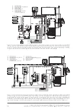
Page 27: ...runs the speed controlled hot water circulation pump If temperatures in the primary buffer cylinder are sufficient solar heat is used for heating by raising the heat ing return temperature 9 System Solutions Example RATIO H PG RATIOfresh T P2 T T Vm T T SUNGO P4 P5 HKM P1 P1 CIRCO P3 Solar controller T storage Heating circuit Collector field P1 Solar circuit pump P2 Cylinder charge pump P3 Heating...

Page 28: ...ge is utilized for space heating The solar controller additionally controls loading of the buffer via the fireplace inset Tvl SUNGO Vu Ta Ttw P1 P1 CIRCO P4 P3 Vr B A AB P2 P5 RATIOfresh RATIO H PG Heating circuit Solar controller T storage Collector field Oil or gas heating boiler Cold water Hot water P1 Solar circulation pump P2 Buffer discharge pump to heat potable water P3 Cylinder charge pump...

Reviews: