EN-RATIOfresh-250-400_TI-MA-0809-11214900
7
Standby Temperature Control
The RATIOfresh freshwater station is also equipped with a
standby temperature control in addition to the circulation
function. The control activates the primary pump and sup-
plies the station with hot water to maintain the preset
standby temperature at the primary flow outlet port re-
gardless of a withdrawal of hot water.
This function serves to preheat the plate heat exchanger;
this means that hot water is thus much more quickly avail-
able at the desired nominal temperature in case water is
withdrawn. This function also protects from frost if the
standby temperature is set to a lower value of 10 °C. The
standby temperature control is only activated if the cylin-
der temperature is sufficiently high.
2.3 Standards and Guidelines
The following standards and guidelines must be observed
and complied with when installing hydraulics and/or per-
forming electrical wiring: IEC 364 or CENELEC HD 384,
DIN VDE 0100 and IEC-Report 664, DIN VDE 0110 and na-
tional accident prevention rules and regulations, as well as
VDE 0100, VDE 0160 (EN 50178), VDE 0113 (EN 60204),
and local rules and specifications of your energy provider
or utility company.
Specifications outlined by DVGW W551 concerning pro-
tection from the Legionella pneumophila bacteria must be
observed for multi-family home installations. A circulation
must be operated between hot water heater and tapping
point for potable water volumes greater than 3 liters. The
hot water outlet temperature of the RATIOfresh station
must always be set to
≥
60 °C.
2.4 Installation Recommendations
The tank must be installed in a frost-free room with short
lines to the consumer.
De-energize the control unit as outlined by the manual be-
fore working on the pump or the control unit. Controller
and pump carry electricity even if the controller switches
the pump off!
Cold and Hot Water Line
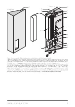
A safety valve (cf. fig. 5) is required in the cold water supply
line as specified by DIN 4753 T1. A min. thread diameter of
DN 15 must be selected for a heating output of max. 75 kW.
The safety valve can be omitted only if a type approved flow
monitor limits the water temperature to 95 °C. The valve
must be designed for a blowing-off pressure that corre-
sponds with the permissible working overpressure. In case
of 10 bar and higher waterline pressures, install a pressure
reducer behind the water meter. When heating the fresh-
water station without water tap, water is dripping out off the
safety valve. Use a siphon funnel to catch and dispose off
this water.
Do not install a shut-off between safety valve and freshwa-
ter station. A drain valve should be installed for mainte-
nance and service tasks. The functionality of the safety
valve must be checked regularly in accordance with DIN
4753. The exhaust vent may never be closed or restricted. A
corresponding water filter meeting current technology
standards is to be installed into the cold water supply line.
Connecting the Circulation
The freshwater station RATIOfresh is designed to be con-
nected to a circulation line. The circulation pump must be a
commercially available stepped wet pump. E-pumps or
pumps with integrated motor protection or ON/OFF
switching electronics may not be operated.
Connecting the Primary Circuit
The piping of the primary circuit should be as short as pos-
sible to achieve the rapid heating of the heat exchanger
when water is tapped. The max. permissible pressure loss
within the primary circuit may not be exceeded when lines
are longer.
A bleeder is to be installed at the highest point of the pri-
mary circuit. The primary flow should be withdrawn at the
hottest point of the buffer storage tank, and the primary re-
turn should be returned as close to the bottom of the buffer
storage tank as possible.
Gravity circulations may occur depending on the length,
design, and insulation state of the primary circuit. This con-
tinuously withdraws energy from the standby section of the
buffer cylinder.
A gravity brake with low admission pressure must be in-
stalled on-site in addition.
Thermal Disinfection / Protection from Legionella
Pneumophila Bacteria
Please note that the “Disinfection” function only can be
used as intended if the cylinder temperature sensor can
correctly measure the derivative temperature within the
connected auxiliary heating range. The sensor should thus
be attached 10 cm below the actual tapping point on the
buffer cylinder (on the tank wall as depicted in fig. 7).
Please also note that increased temperatures within the hot
water network and associated pipes pose a risk of scalding
injuries while the disinfection program is running!
Protection from Corrosion and Lime Buildup
All water-conducting parts are basically subject to corro-
sion and lime buildup, especially if temperatures exceed
60 °C and with aggressive water. Hot water temperatures
thus should never exceed 60 °C. Significant lime deposits
are not expected with carbonate hardness below approx.
10° dH and temperatures less than 60 °C. If your potable
water is harder than this, we recommend on-site lime
buildup reducing measures. If the plate heat exchanger
must be decalcified on a regular basis, irrigation cocks (fig.
6) should be installed during the system assembly.
The plate heat exchanger of your freshwater station is
made from copper soldered stainless steel plates. Steel
pipes may thus not be used in the flow direction (towards
the freshwater station) since copper is water soluble in
minute particles and causes pitting when deposited on
steel.
Water with low hydrocarbon content and high portion of
neutral salts (e.g. soft water containing chloride) can cause
dezincification of the installed brass elements.


