EN-RATIOfresh-250-400_TI-MA-0809-11214900
9
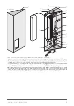
3.4 Connecting Potable Water (fig. 6)
Cold and hot water connections must be connected to the
freshwater station in accordance with the rules and regula-
tions issued by the local water utility or water provider. We
recommend connecting to the potable water network in
the manner illustrated in fig. 6.
●
A safety subassembly
(3)
with safety, shut-off, and check
valve must be installed in the cold water supply
(2)
in
acc. with DIN 1988. Make sure there is no shut-off be-
tween the RATIOfresh station
(1)
and the safety sub-
assembly
(3)
. To connect the piping to the cold water
supply
(7)
of the station, please use the connection sets
with 1" swivel nuts
(4)
, soldered connection 22 mm
(5)
,
and flat seal
(6)
or threaded connection sets as an alter-
native, both available as additional accessories.
●
The hot water outlet of the station
(8)
must be connected
to the hot water network with soldered or threaded con-
nection sets and well insulated as well. Do not forget flat
seals
(6)
!
●
Potable water with a high content of lime may require
that the heat exchanger is flushed regularly. This re-
quires installing irrigation cocks
(9)
and
(10)
into the
cold and hot water lines in close proximity to the station!
After irrigation cock
(10)
in the hot water line, an addi-
tional shut-off cock
(11)
is needed for flushing the pipes.
3.5 Connecting Circulation
(Optional, fig. 6)
DVGW 551 specifies a circulation element or system in
larger hot water networks. The circulation return
(21)
must
be installed directly before tapping point
(22)
. The circula-
tion pump
(23)
is supplied with voltage and controlled by
the controller. Chapter 3.7 provides information about the
correct connection of the power cable
(24)
. Please note
that a backflow preventer (integrated in the figure of the cir-
culation pump) must be installed in the circulation line.
●
Remove the 1/2" plug
(26)
at the circulation return con-
nection of the station
(25)
and attach the circulation re-
turn line as per connection diagram. Use a 1/2" threaded
connection
(27)
.
Wa
gn
er
&
Co
1
8
7
25
6
5
4
10
11
24
21
6
5
4
9
3
1/2 AG
22
26
27
23
KW
2
Figure 6 Potable water connection
1
Bottom section of housing;
2
Cold water supply;
3
Safety subassembly;
4
1" swivel nut;
5
22-mm soldered connection;
6
Flat seal;
7
Cold water supply;
8
Hot water outlet;
9
Irrigation cock;
10
Irrigation cock;
11
Shutoff valve;
21
Circulation return;
22
Tapping point;
23
Circulation pump;
24
Connection cable to circulation pump;
25
Circulation return connection;
26
½" plug;
27
½" threaded sleeve.


