18
EN-USA_SECUSOL_TI-MA-111013-1121R800
2.5 Pre Installation Notes
Risk of burns at collector connections!
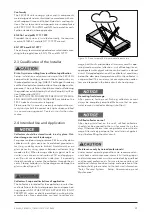
Collector connections can get very hot as soon as un-
covered collector is exposed to the sun (figure 3). Wear
gloves!
Danger of open injuries!
Always wear gloves to avoid severe cuts and lacerations
when working with sharp edged metal sheets and com-
ponents!
Risk of damage to absorber!
Remove protective plastic caps from connections before
collector is exposed to the sun. Risk of molten plastic
entering and damaging the absorber!
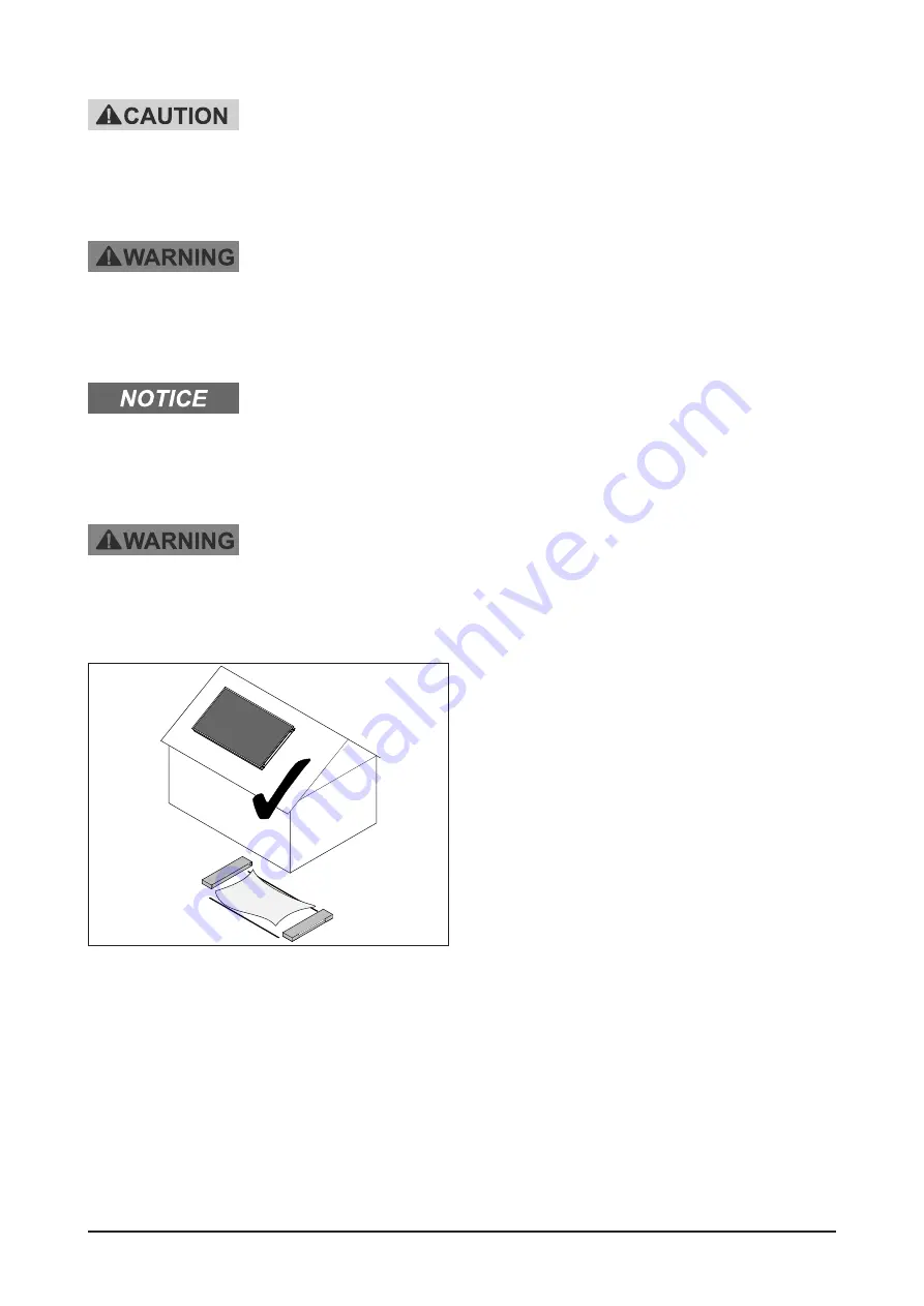
Risk of suffocation!
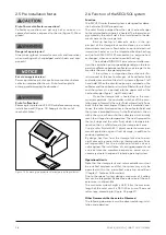
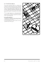
Remove glass protection PE-LD film before commencing
installation work! (Figure 14) Keep plastic film out of
reach of children!
2.6 Function of the SECUSOL system
Function
The SECUSOL solar thermal system is designed for dome-
stic hot water (DHW) preparation.
The solar fluid is pumped from the solar heat exchanger
to the solar collector where it is heated. The thermal ener-
gy carried by the solar fluid is then transferred to the do-
mestic water in the storage tank.
Backup heating of domestic water in the up-
per part of the storage tank can be done via a suitable
downstream continuous flow heater, an optional electrical
immersion heater or via the integrated backup heating
coil (not with SECUSOL 250 monovalent, i.e. only one heat
exchanger), when connected to central heating.
The included SUNGO US plus solar controller con-
trols the circulation pump speed depending on the tem-
perature difference between collector and storage. It also
monitors the max. storage temperature.
If the system is in stagnation, the entire solar flu-
id is moved to the heat exchanger, while collector field
and collector circuit are filled with system air (figure 7, left
hand side). When the circulation pump is switched on, the
collector and the collector circuit are filled with solar fluid
and the system air is pushed into the upper coils of the
heat exchanger (figure 7, right hand side).
Once the storage tank is heated up to the maxi-
mum temperature, the controller switches off the circu-
lation pump. Normally the solar fluid automatically flows
back to the heat exchanger. Otherwise if irradiation con-
tinues, the solar fluid vaporizes in the collector field and
the system is emptied this way. As the fluid retreats, the air
within the system flows into the collectors which quickly
reach their stagnation temperature. The heat transport to
the tank stops and the solar fluid, which is temperature-
sensitive, then is safely stored in the storage tank area.
Using a solar fluid with 33 % glycol content ensures per-
manent protection against frost damage, in addition to
corrosion protection.
By design heat loss from the storage tank due to over-
night convective recirculation or thermosyphonic flows
are impossible. Thus the installation of check valves is
not required. The installation of venting equipment and
a service-intensive membrane expansion vessel are un-
necessary due to the special 2-phase operating system.
Operational Limits
Note that the storage tank and solar controller must not
be installed outdoors and that the system may only be
operated within the permitted operating conditions
(Chapter 1: Technical Information).
Due to the special system design a maximum of 2 collec-
tors can be integrated. Retroactive extension of the coll-
ector area is not possible.
The maximum system height is 28 ft / 8.5 m, the maximum
length of the solar circuit is 98 ft / 30 m (sum of flow and
return legs, according to (Figure 28 page31).
Other Documents that have to be Observed
The following documents must be observed during instal-
lation and operation:
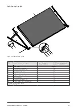
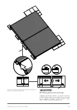
Figure 14 Remove glass protection film before installing collector!


