EN-USA_SECUSOL_TI-MA-111013-1121R800
21
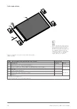
B
A
B
12.5 lb-ft (17 Nm)
22.1 lb-ft (30 Nm)
C
C
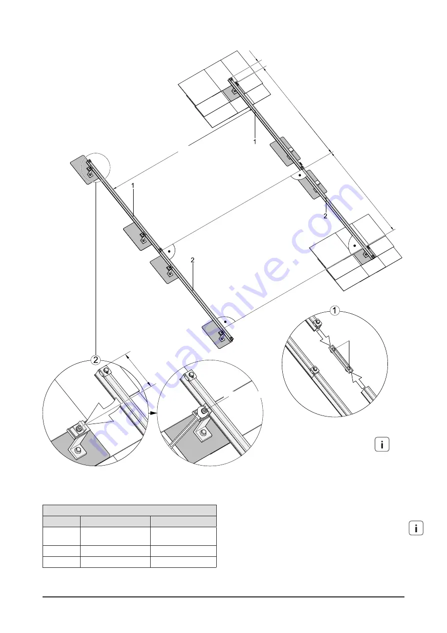
Table 12 Distance in inch / mm
Segment
EURO C20 AR-M
EURO L42
A
63 in - 74.8 in
1600 mm – 1 900 mm
59 in - 66.9 in
1500 mm – 1 700 mm
B
max. 47.2 in / 1200 mm
max. 47.2 in / 1200 mm
C
max. 8 in / 200 mm
max. 8 in / 200 mm
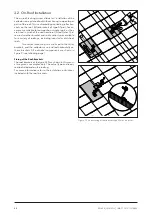
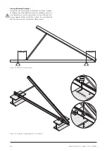
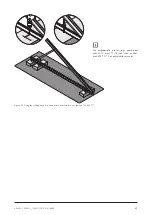
Already connect the rails
while still on the ground
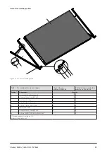
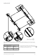
Figure 16 Overview of rail installation (upper image; collector clamps are pre-assembled).
(1)
supporting rail “1” fixed with two roof brackets
and holding two collector clamps
(2)
supporting rail ”2“ fixed with rail connector to upper rail and one roof bracket; rail “2” holds one collector
clamp.
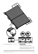
For the side by side installation of two collectors the four
supporting rails of type 1 (see figure 14) must be aligned
at the given distance (see figures 5 and 6).
Installation of the Rails


