EN-USA_SECUSOL_TI-MA-111013-1121R800
29
3.4 General Notes about Storage
Installation
The pre-assembled return flow sub-assembly has a 12
mm pipe nozzle on the solar circuit side (
➊
) --> Numbers
in black circles refer to Figure 26.
3.5 Setting up the Storage Tank
Please observe the following when setting up the storage
tank (Figure 8 page9):
The tank insulation consists of 3 parts, the tank insulation
(1), the cover insulation (2) and the pre-installed ground
insulation (3).
●
Remove the tank insulation, the storage cylinder lid (4)
as well as the cover insulation and put safely aside.
●
Unscrew cylinder (6) from the pallet and carry to its final
position. Note that the enamel coating of the storage
tank can be damaged if jolted.
●
Remove 1“ NPSM plug (10) from the pallet and put
aside.
●
Place the storage cylinder so that the connections will
face the wall.
●
During transport a cable binder is used to secure the
pre-wired controller at the cylinders hoisting lug. Cyl-
inder temperature sensor and pump control cable also
are pre-wired.
3.6 Connection to Domestic Water
Supply
Hot and Cold Domestic Water
Cold and hot water connections must be done according
to the rules and regulations of your local water supplier.
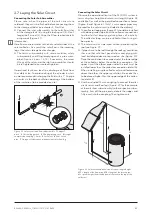
We recommend the connection as shown in Figure 26
●
Connect a safety subassembly (2) with a safety valve
and a non-return valve according to DIN 1988 to the
cold water inlet of the tank (
➋
).
Within the United States
the installation of an IAPMO compliant backflow pre-
venter is mandatory for all installations connected to
the drinking water supply.
Risk of serious scalding for the end user!
Water temperatures at hot water taps can reach up to
203 °F / 95 °C!
A thermostatic mixing valve must be installed to avoid in-
juries to end customers!
●
It is absolutely necessary to install a thermostatic mix-
ing valve (3) since temperatures during the summer
months can reach up to 203 °F / 95 °C at the hot water
outlet.
➐
Without thermostatic mixing valve there is a
considerable risk of scalding. The thermostatic mixing
valve can be connected between safety subassembly
(2) and the cold water connection at the storage tank
➋
using a T-piece.
●
Close the 1" NPSM socket
➍
with the plug and seal
thoroughly. Alternatively an electrical immersion heat-
er is available which can be installed in this socket, as
outlined in the chapter “Backup Heating”.
●
Re-tighten bolts around flange cover (6) to ensure leak-
age-free operation.
Re-Circulation
The return leg (8) should be led away just before the tap-
ping point (10). The circulation pump (9) should be cont-
rolled according to the hot water temperature at the most
distant tap (sensor 11). We recommend that the circula-
tion should be returned to the cold water inlet (4) of the
thermostatic mixer (3). A check valve should be installed
in the circulation pipe. Please note that circulation can
cause significant loss of heat. Hint: use a time, tempera-
ture or tap-event controlled circulator.

