EN-USA_SECUSOL_TI-MA-111013-1121R800
37
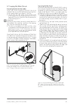
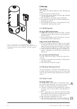
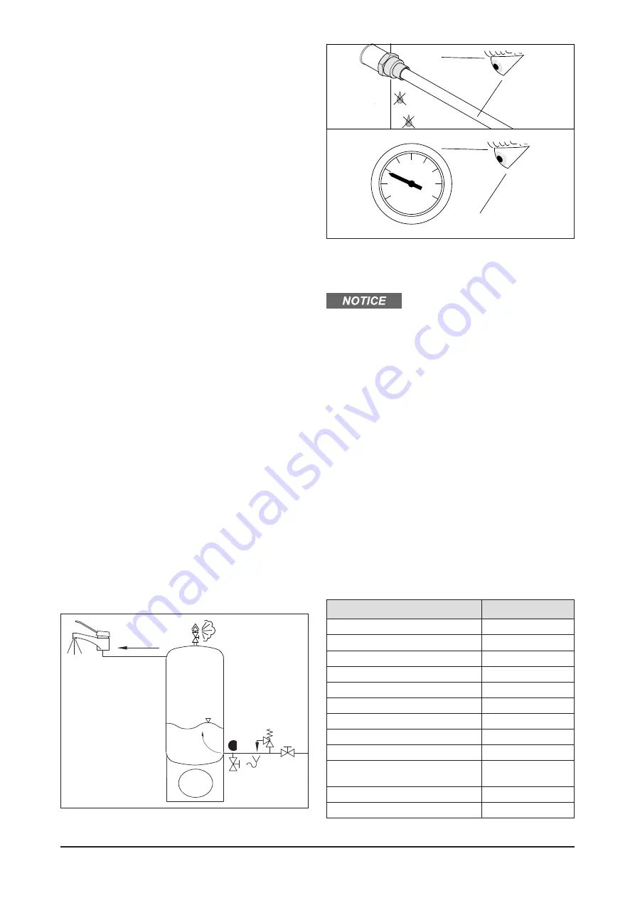
Figure 37 Filling and venting of the storage cylinder
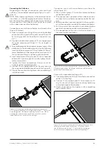
Figure 38 Check connections for tightness, re-tighten if required;
monitor system pressure
bar
is rinsed. Continue the rinsing process until the flow-
ing out liquid is clear, i.e. does not contain any visible
residues.
●
If the collector loop pipes were soldered, the collector
loop also must be rinsed prior to connecting it to the
storage tank. After rinsing, some unwanted domestic
water residues may remain in the system. Therefore
blow forcefully into the end of the hose mounted on
the flow sub assembly to empty the collector loop pipe.
To avoid corrosion, the system must be filled with frost
resistant solar fluid immediately after rinsing.
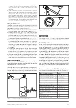
Filling the Solar Circuit
To protect the system against frost damage, only use the
solar fluid included in the delivery. Follow the steps men-
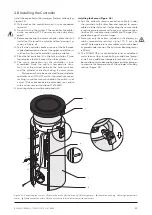
tioned below to fill the system (Figure 40):
●
Observe the included technical information and mate-
rial safety advice “Solar Heat Transfer Liquid DC 20 F”.
●
Remove canister with DC 20 F (7) from the box and
empty the content (2.5 liters) into a container (6) with a
minimum capacity of 10 liters. Add one full canister (5 li-
ters) of water and stir. The solar liquid mix contains 33%
Glycol guaranteeing frost protection to 1.4 °F / -17 °C.
●
Connect hose (2) with a ½" swivel nut to the cold water
filling and emptying tap at the bottom (3). Place the
other end of the hose into the container (6). Place the
container in a higher position than the solar inlet con-
nection (5). A transparent hose is useful to monitor the
filling level.
●
Connect the second hose (4) to the flow connector
and briefly suck on the hose end. Place the end in the
empty canister (7) and place it on the floor. The solar
liquid automatically siphons into the heat exchanger.
●
After the heat exchanger is filled completely and solar
fluid flows into the hose (4), the two filling taps on the
solar return (3) and the solar flow (5) must be closed.
Setting up the controller
For the operation of the SECUSOL system, special settings
at the controller are required. Please observe the separate
controller manual "SUNGO US plus“.
Switch on the SUNGO US plus controller. The default sys-
tem is the system 1, but the systems 2, 3 and 8, which
are also preset with the value of the Secusol drainback-
system, can be selected as well.
2
The systems 4, 5, 6, 7, 9 and 10 should not be selected
because they are not compatible with the Secusol-system.
Controller Operation:
When the temperature difference between collector
and storage tank bottom is continuously higher than the
switch-on temperature (DT O) for 30 seconds or more,
the controller output R1 switches the pump fully on for a
defined filling time (tFLL). After the filling time the switch-
off conditions will be ignored for a stabilization intervall
of 1 minute (tSTB), in order to avoid a premature system
shutdown, before the controller automatically switches to
normal operating mode. The pump speed varies within
the defined speed interval (nMN: 30% and nMX: 50%) ac-
cording to the collector and tank temperature. The cont-
roller output R1 switches off the solar pump if the tempe-
rature difference between the collector and the storage
tank falls below the specified switch-off temperature dif-
ference (DT F) or if the maximum store temperature (S MX)
is reached.
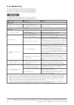
We recommend the specific SECUSOL settings for the so-
lar circulation pump and the controller acc. to Table 14.
Table 14 Controller settings
value
Switch-on temperature difference (DTO)
25.0 °Ra [12.5 K]
Switch-off temperature difference (DTF)
6.0 °Ra [3.0 K]
Nominal temperature difference (DTS)
30.0 °Ra [15.0 K]
Rise control (RIS)
10 °Ra [5 K]
Minimum speed pump (nMN)
30%
Maximum speed pump (nMX)
50%
Maximum tank temperature (SMX)
180 °F [82 °C]
Emergency temperature, collector (EM)
275 °F [135 °C]
Drainback option (ODB)
On
ODB switch-on condition time period
(tDTO)
30s
ODB filling time t(FLL)
2mn
ODB stabilization time (tSTB)
1mn

