EN-USA_SECUSOL_TI-MA-111013-1121R800
39
7 Maintenance and Care
Some components of the SECUSOL system are subject
to wear and have to be serviced regularly by expert per-
sonnel and, if required, replaced timely. See table 12 for a
list of wear components. For checking the sacrificial ano-
de the flange cover has to be opened. The flange cover
sealing and all flat sealing gaskets must be renewed after
each opening. See also tab. 8 on page 12.
Annual service checks are required, otherwise the warran-
ty is void:
●
Check for leaks at the storage cylinder and all connec-
tions. Look for signs of scaling or moist sections on the
insulation. Re-tighten connections if required.
●
Vent storage cylinder (follow steps as in chapter 4).
Hereunto remove storage lid and lid insulation.
●
To check the protective anode, the cold water supply
must be shut off at the safety valve. A cock must be
opened that is situated below the hot water connection
nozzle
➐
. Afterwards remove the protective anode:
Open the flange cover for SECUSOL 250 and 350. The
flange gasket has to be renewed after each opening
(see Table 10 accessories, on page 12).
●
Check the protective anode.
If the substance of the anode is degraded, it has to be
replaced. Otherwise re-install the anode and vent the
pipe circuit. (Chapter 4).
●
Check the solar liquid according to the technical in-
formation “Solar Heat Transfer Liquid DC20 F” If the
PH Value drops below 6.6 or frost protection does not
reach -17 °C, the solar liquid should be replaced. If the
liquid has a stingy smell or black coloration, it also has
to be replaced.
●
Fill in and sign the maintenance records.
Table 12
Wear parts
Component
Inspection interval
Sacrificial anode on tank
Bi-annual inspection – durability is
dependent on domestic water quality,
2 - 10 years
Flange cover sealing
Renew after each opening
Flat seals on pipe
connectors
Renew after each opening
Solar fluid
Bi-annual inspection according to
data sheet DC20 F: pH value > 6.6
and frost protection up to a minimum
of 1.4 °F /-17 °C, otherwise replace
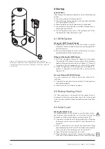
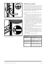
Figure 41 Attaching the jacket insulation by locking the hook
closure.
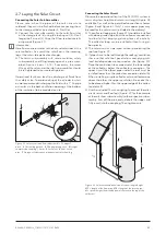
Figure 42 Insulation of the pipe connections overlapping with the
storage cylinder jacket insulation .


