


14
Finish 230 AC Compact
GB
Maintenance
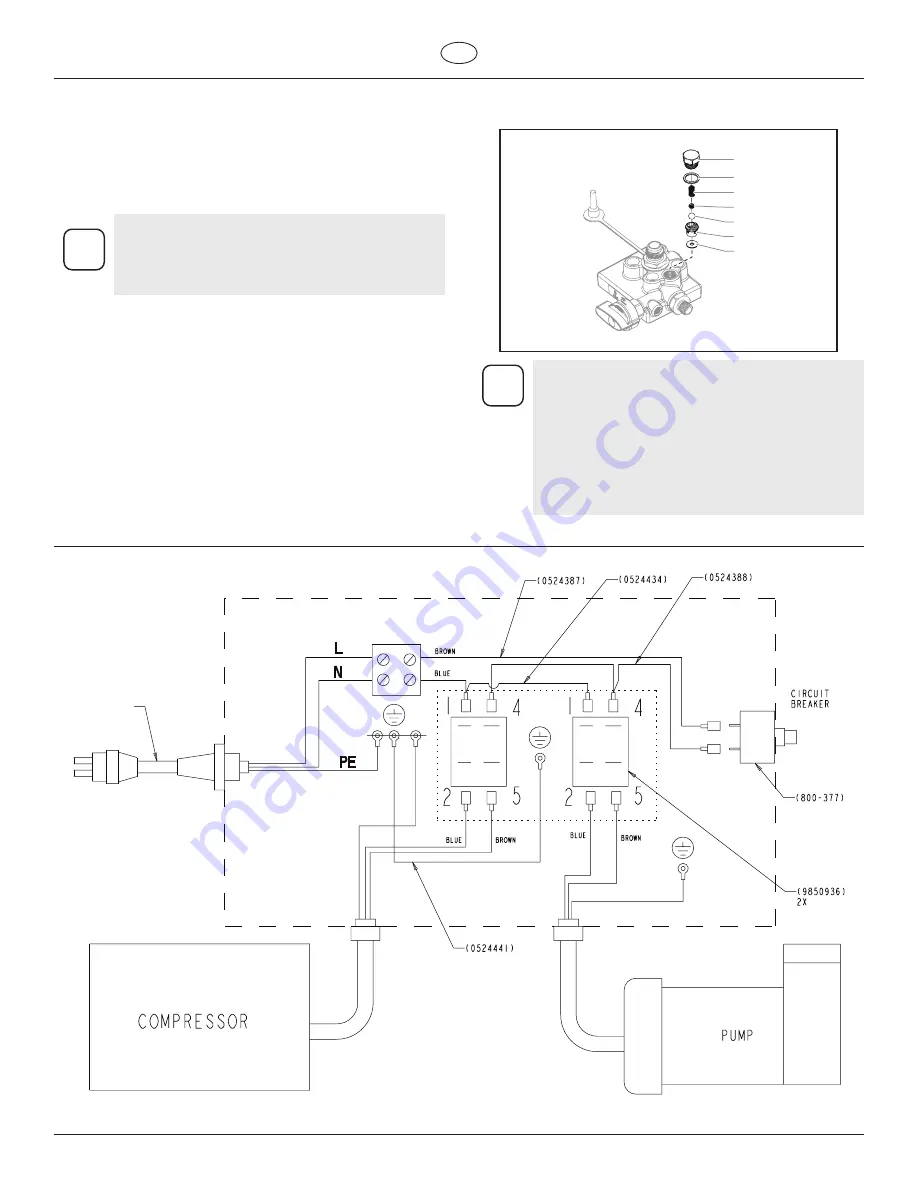
Electrical Schematic
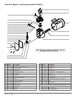
8. Tighten the outlet valve nut (a) securely with an adjustable
wrench. Do not over-tighten.
(b)
(a)
(c)
(d)
(e)
(f)
(g)
i
Wear on the ball is almost impossible to detect
visually. To test for a worn outlet valve assembly,
turn the pressure control knob clockwise to its
highest setting and run water only through the
pump for 10 to 15 minutes without triggering the
gun.
If the valve is defective, the end cap will get very hot
to the touch. If it is functioning properly, it will stay
approximately the same temperature as the water
running through it.
8.2
Removing and Cleaning the Outlet Valve
It may be necessary to remove and clean the outlet valve or to
replace parts inside the valve worn out through normal use.
1. Remove the outlet valve nut (a) with a wrench.
2. Remove and clean the ball stop (d) and small spring (c) inside
the valve using a wire hook or tweezers. Replace the spring if
it is broken or worn.
i
This spring is manufactured to a very specific
tension. Do not stretch the spring. Do not put in
an unauthorized substitute. See the paint pump
assembly parts diagram for the proper replacement
part number.
3. Remove the seat (f) and ball (e) assembly.
4. Clean all parts thoroughly. If the ball or seat show any sign of
wear or damage, replace them with new parts. This carbide
ball must seal tightly against its seat for the valve to function
properly.
5. Cover all parts with a thin coat of light oil before reassembling.
6. Drop in the valve ball (e).
7. Insert the protector (f) and spring. Be sure that the O-ring (b) is
positioned properly and that the tongue on the cap fits inside
the spring.
(See parts list)
9.
Electrical Schematic


