


6
Finish 230 AC Compact
GB
Safety Regulations
General Description
1.2
Earthing Instructions
Electric models must be earthed. In the event of an electrical short
circuit, earthing reduces the risk of electric shock by providing an
escape wire for the electric current. This product is equipped with a
cord having an earthing wire with an appropriate earthing plug. The
plug must be plugged into an outlet that is properly installed and
earthed in accordance with all local codes and ordinances.
DANGER — Improper installation of the earthing
plug can result in a risk of electric shock. If repair
or replacement of the cord or plug is necessary, do
not connect the green earthing wire to either blade
terminal. The wire with insulation having a green
outer surface with or without yellow stripes is the
earthing wire and must be connected to the earthing
pin.
Check with a qualified electrician or serviceman if the earthing
instructions are not completely understood, or if you are in doubt as
to whether the product is properly earthed. Do not modify the plug
provided. If the plug will not fit the outlet, have the proper outlet
installed by a qualified electrician.
Caution – The power cord for this equipment acts as
an emergency stop/emergency switching off device.
The power cord must be placed near an easily
accessible, unobstructed socket-outlet.
1.3
Technical Data
Weight
: 40.6 kg (89.5 lbs.)
Capacity
: Up to 1.69 liters (0.45 gallon) per minute
Power requirement
:
Model 0524009
: 10 amp minimum circuit on 230-240 VAC,
50 Hz current, 1 PH
Model 0524019
: 10 amp minimum circuit on 230 VAC, 50 Hz
current, 1 PH
Power consumption
: 1000W
Short circuit current
(SCC)
: 8 amp
Max. fluid pressure
: Up to 193 bar (19 MPa, 2800 PSI)
Max. air pressure
: Up to 2.1 bar (0.21 MPa, 30 psi)
Dimensions
: 81.3 cm x 53.3 cm x 55.9 cm (32” L x 21” W x
22” H)
Noise level
: less than 70dB (A).
Vibration levels
Spray gun
: < 2.5m/s
2
Cart handle
: 6.5m/s
2
when unit is operating
2.
General Description
This fine finish spray system is versatile enough to use for low
pressure fine finish work as well as high pressure airless spraying. The
system includes a diaphragm paint pump and an air compressor that
work together to provide this versatility.
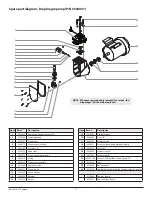
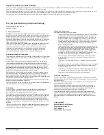
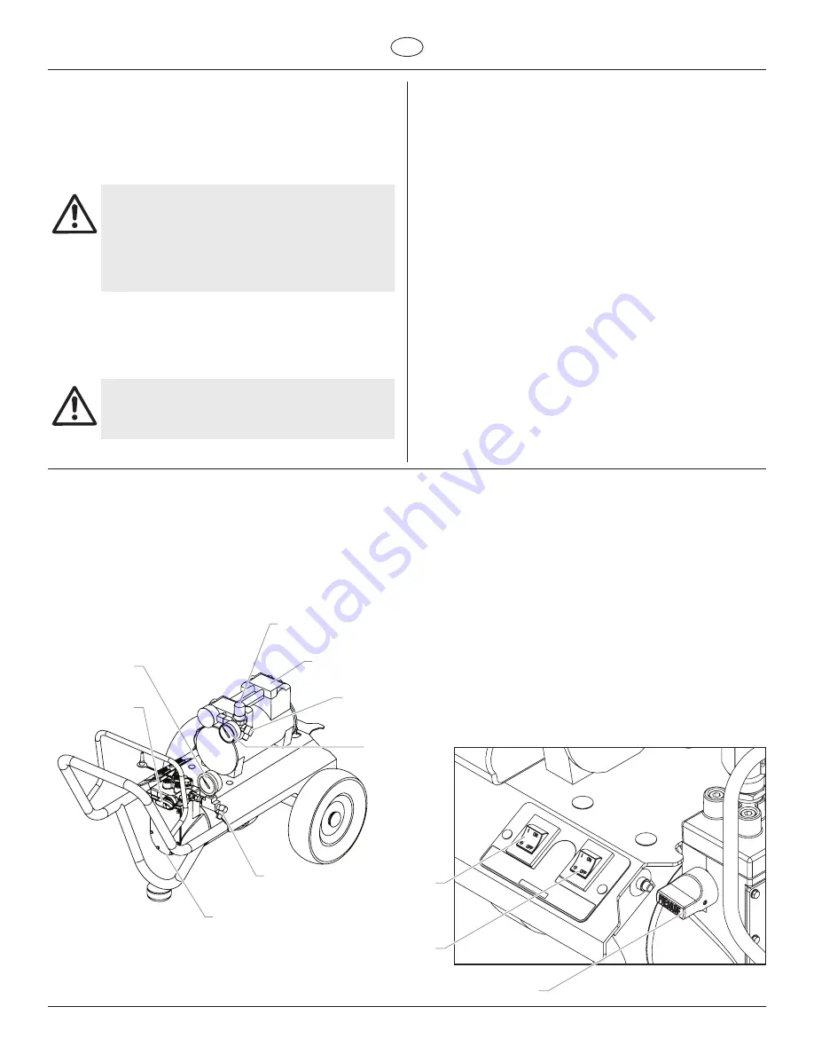
2.1
System Diagram
1
9
10
11
2
8
7
6
4
5
3
1
9
10
11
2
8
7
6
4
5
3
1 Material pressure gauge
2 PRIME/SPRAY valve
3 Air pressure regulator
4 Air compressor
5 Air outlet fitting
6 Air pressure gauge
7 Material outlet fitting
8 Diaphragm pump
9 Compressor ON/OFF switch
10 Diaphragm pump ON/OFF switch
11 Pressure control knob


