background image


Finish 230 AC Compact

GB

Operation 

4. 

Operation

Use the following procedures to operate the spray system.

4.1 

Preparing to Prime

  1.  Fill the inlet valve with water or with a light household oil.
  2.  Make sure that the PRIME/SPRAY valve is set to PRIME and that 

the pressure control knob is turned counterclockwise to its 

lowest pressure setting.

  3.  Turn on the pump by moving the pump ON/OFF switch to the 

ON position.

  4.  Increase the pressure by turning the pressure control knob 

clockwise 1/2 turn.

  5.  Force the inlet valve to open and close by pushing on it with a 

screwdriver or the eraser end of a pencil.  It should move up and 

down about 1.5 mm.  Continue until water or oil is sucked into 

the pump.  This will wet the moving parts and break loose any 

old paint residue.

  6.  Put the palm of your hand over the inlet.  Turn the pressure 

control knob clockwise to its maximum setting.  You should 

feel suction coming from the inlet valve.  If you do not, refer to 

the “Removing and Cleaning the Outlet Valve” procedure in the 

Maintenance section.

  7.  Turn the pressure control knob counterclockwise to the 

minimum pressure setting.

  8.  Turn the pump ON/OFF switch to OFF.

4.2 

Priming with Hopper Assembly

  1.  Attach the hopper assembly to the pump.
 

a.    Screw the return tube fitting into the return tube port on 

the side of the pump.

i

Do not over-tighten.  Hand tighten only.  Some 

threads will be visible even when fully tightened.


b.    Thread the return hose onto the return hose fitting on the 

pump.


c.    Turn the paint hopper clockwise to thread it onto the inlet 

valve.  Continue to turn the paint hopper until it is secure 

on the inlet valve.

i

Make sure the threads are straight and the hopper 

turns freely on the inlet valve.  Do not cross-thread.


d.    Place the filter screen into the bottom of the paint hopper 

and snap it in position.


e.    Make sure that the motor ON/OFF switch is turned to OFF.


f.    Place the straight end of the return tube into the return 

tube fitting.


g.    Thread the nut on the return tube fitting and tighten until 

the return tube is secure.


h.    Place the hook end of the return tube into the hole in the 

paint hopper cover.

  2.  Turn the pressure control knob counterclockwise to its lowest 

pressure setting.

  3.  Remove the paint hopper cover and fill the paint hopper with 

material or place the suction set into a bucket of material.

  4.  Turn the PRIME/SPRAY valve to PRIME.
  5.  Move the motor ON/OFF switch to ON.
  6.   Turn the pressure control knob clockwise to between half and 

full pressure.  Let the unit prime 1 to 2 minutes after material 

begins to flow through the return tube.

1

2

5

4.1

4.1

4.2

1a

1f

1b

1g

1c

1h

Attention

Always reduce the pressure to zero by triggering 

the spray gun before changing the position of the 

PRIME/SPRAy valve.  Failure to do so may cause 

damage to the paint pump diaphragm.

If the pressure control knob is reduced to zero and 

the PRIME/SPRAy valve is still on SPRAy while the 

pump is operating, there will be high pressure in the 

hose and spray gun until the PRIME/SPRAy valve is 

turned to PRIME or until the spray gun is triggered to 

relieve the pressure.

Summary of Contents for 524009

Page 1: ...Edition 4 2012 0524 831F GB Operating Manual Models 0524009 0524019 Finish 230 AC Compact Spray System...

Page 2: ...nform the doctor about the coating material or solvent used The operating instructions state that the following points must always be observed before starting up 1 Faulty units must not be used 2 Secu...

Page 3: ...6 Spraying Technique 11 7 Cleanup 12 7 1 Overnight storage 12 7 2 Long Term storage 12 7 3 Clearing the paint hopper 12 7 4 Clearing the optional suction set 12 7 5 Clearing the spray hose 12 7 6 Fina...

Page 4: ...R aim the gun at any part of the body NEVER allow any part of the body to touch the fluid stream DO NOT allow body to touch a leak in the fluid hose NEVER put your hand in front of the gun Gloves will...

Page 5: ...are not compatible with aluminum and may cause an explosion If you are unsure of a material s compatibility with aluminum contact your coating s supplier HAZARD HAZARDOUS VAPORS Paints solvents insec...

Page 6: ...lectrician Caution The power cord for this equipment acts as an emergency stop emergency switching off device The power cord must be placed near an easily accessible unobstructed socket outlet 1 3 Tec...

Page 7: ...h all of its functions and corresponding safety information 6 Attach the spray hose to the material inlet fitting on the spray gun Using two wrenches one on the gun and one on the hose tighten securel...

Page 8: ...nto the return hose fitting on the pump c Turn the paint hopper clockwise to thread it onto the inlet valve Continue to turn the paint hopper until it is secure on the inlet valve i Make sure the thre...

Page 9: ...control knob counterclockwise to the minimum pressure setting Attention Always reduce the pressure to zero by triggering the spray gun before changing the position of the PRIME SPRAY valve Failure to...

Page 10: ...ed size and atomization Use the pressure control knob to control the flow of paint to the gun Use the air pressure regulator to control the amount of atomization air available to the gun Use the patte...

Page 11: ...lock before removing replacing or cleaning tip 6 Spraying Technique The key to a good paint job is an even coating over the entire surface Keep your arm moving at a constant speed and keep the spray g...

Page 12: ...urn the pressure control knob to 1 2 maximum pressure This will draw the remaining material in the paint hopper through the pump up the return tube and into the material container 8 Turn the pressure...

Page 13: ...and oiling of the pump after use are the most important steps to perform to insure proper operation after storage 8 Turn the pressure control knob counterclockwise to its lowest setting 9 Turn the PRI...

Page 14: ...rn out through normal use 1 Remove the outlet valve nut a with a wrench 2 Remove and clean the ball stop d and small spring c inside the valve using a wire hook or tweezers Replace the spring if it is...

Page 15: ...he compressor ON OFF switch is in the OFF position 2 Compressor ON OFF switch is faulty 3 Compressor is faulty 4 Relief hole under air regulator is blocked 1 Air regulator setting is too low 2 Paint i...

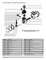
Page 16: ...12 9850936 Pump ON OFF switch 13 0551378 Screw 2 14 0550016 Electrical cover 15 0524733 ON OFF switch label 16 0524242 Hopper assembly 17 0550007 Diaphragm pump 18 0088372 Flat washer 4 Item Part Des...

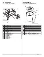
Page 17: ...Pressure regulating spring 8 0089518 O ring 9 0089475 Pressure valve needle 10 0278345 Hydraulic piston 11 0005311 Piston spring 12 0270550 Piston washer 13 0089456 Retainer 14 0278359 Gasket Item Par...

Page 18: ...0508517 Cart weldment 5 0090005 Pad 6 9820305 Washer flat 7 0090026 Screw hex head 8 0551986 Nut with washer 9 0507937 Hose clip 10 9804916 Screw 11 0278373 Wheel 2 12 9805230 Screw Item Part Descrip...

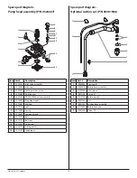
Page 19: ...60 Paint pump 5 0555850 PRIME SPRAY valve assembly 6 0270494 Ring diaphragm 7 0270487 End cap 8 9970103 Seal 9 0270499 Spring 10 0270497 Support spring 11 0270491 Ball 12 0270197 Ball seat 13 0089494...

Page 20: ...di Molgora MB Italia Tel 39 039 625 021 Telefax 39 039 685 18 00 info wagnercolora com CH Wagner International AG Industriestrasse 22 9450 Altst tten Schweiz Tel 41 71 7 57 22 11 Telefax 41 71 7 57 2...

Page 21: ...arantee claims must be made immediately or at the latest within a period of 2 weeks The authorised specialist shop that delivered the device is entitled to accept guarantee claims Guarantee claims may...

Page 22: ...this product is not to be disposed of together with household waste material but must be recycled in an environmentally friendly way Wagner or one of our dealers will take back your used Wagner waste...

Page 23: ...ionale technische Spezifikationen insbesondere GB Declaration of conformity Herewith we declare that the supplied version of Airless high pressure spraying unit complies with the following provisons a...

Page 24: ...que la Airless equipo de pulverizaci n de alta presi n satisface las disposiciones pertinentes siquientes 2006 42 CE 2004 108 CE Normas armonizadas utilizadas particularmente Normas y especificacione...

Reviews: