


ProSpray 3.21
27
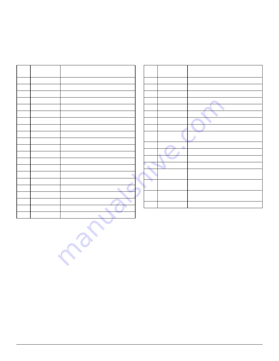
Item
Part No.
Description
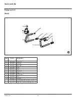
1
0509 594
Retainer
2
0509 584
Piston guide
3
-------
Upper packing
4
0551 756
Transducer assembly
5
0507 517
Pipe plug
6
0290 209
Pump manifold
7
0509 873
Fitting
8
-------
Lower packing
9
0552 489
Bushing
10
0290 277
Piston rod
11
0551 262
Upper cage
12
0551 263
Crush washer
13
50164
Outlet valve ball
14
0551 620
Outlet valve seat
15
13481
Outlet valve retainer
16
0509 591
Lower ball guide
17
0509 583
Inlet valve ball
18
0551 534
Inlet valve seat
19
0509 582
O-ring, Teflon
20
0509 581
Inlet valve seal
21
0290 216
Inlet valve housing
Item
Part No.
Description
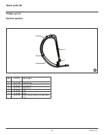
22
9871 160
O-ring
23
0508 748
Filter
24
0508 603
Bearing ring
25
0508 601
Filter housing
26
0508 602
Conical spring
27
0508 749
Bearing spring
28
0508 604
O-ring
29
0507 745
Gasket
30
0558 727
Bypass valve assembly (includes item
29)
31
0507 931
Cam base
32
0508 744
Relief valve knob
33
5006 543
Groove pin
34
9885 612
Return tube fitting
0509 151
Piston assembly (includes items 10-
15)
0290 201
Repacking kit - 1 (includes items 2-3,
8, 11-14 and 16-20).
0558 728
Repacking kit - 2 (includes items 2-3
and 8).
0507 254
Relief valve kit (includes items 29-33).


