background image

Customer Service: 800-880-0993

14

© 2003 Wagner Spray Tech - All rights reserved.

English

D

ISASSEMBLY OF THE

 F

LUID

 S

ECTION

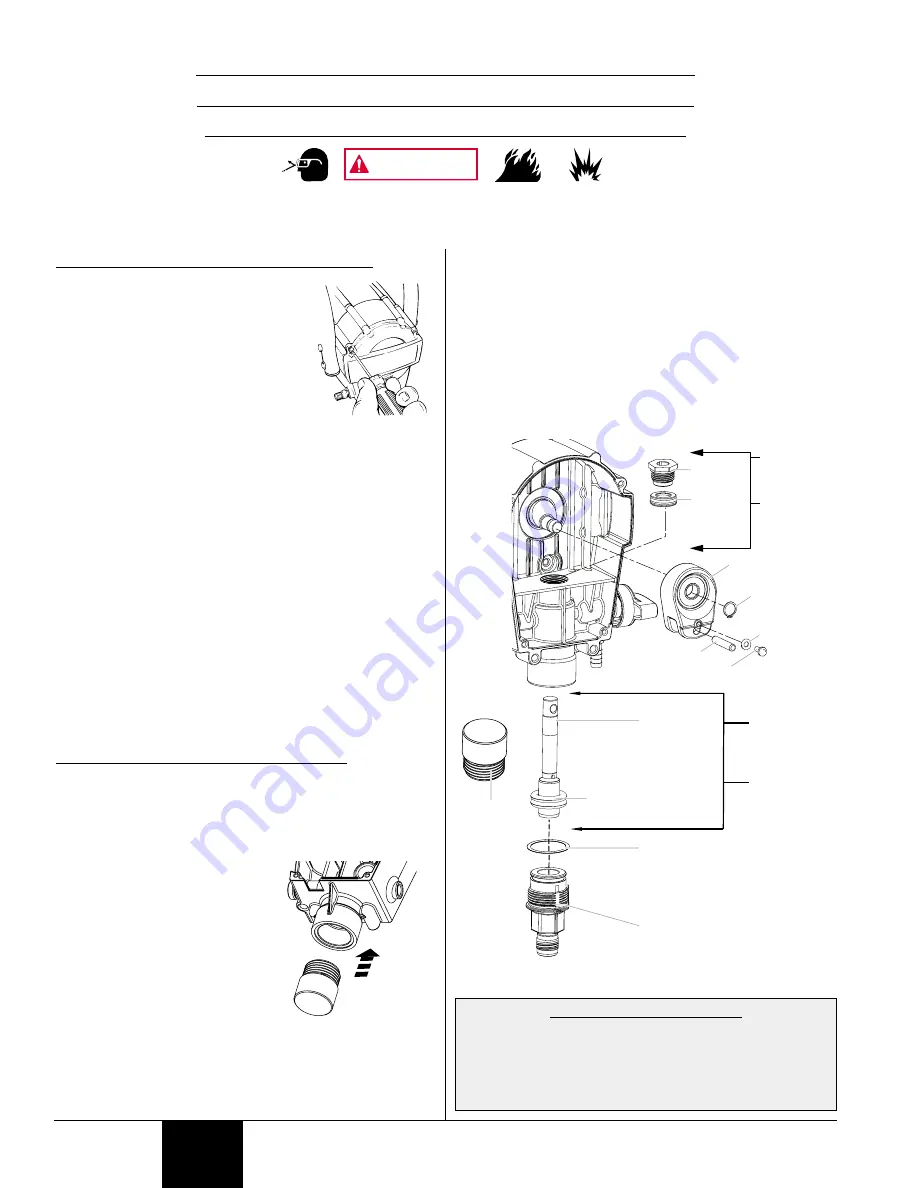
1. Remove the suction set.
2. Remove the front cover and the four

screws that secure it using a T20
Torx head driver.  

3. Remove the yoke screw and washer

that secures the dowel pin.  The
dowel pin connects the yoke to the
piston.

4. Using the pliers, pull the dowel pin

out.

5a. For models 9140, 9140S, and 9150, rotate the pump

shaft so the piston is in the top dead center position.  This
can be done by pushing on the yoke.  This is required to
disassemble all the parts.

5b. For models 9170, 9190, and 9210, inspect the yoke

assembly and piston. In order to remove all the necessary
parts, the piston must not be in the bottom dead center
position.  If the piston is at the bottom of the stroke, install
the front cover and screws, turn the pump on briefly to
index the piston, unplug the unit, and repeat step 2.

6. Unscrew and remove the inlet valve assembly using an

adjustable wrench.  

7. Remove the piston assembly by pushing down on the

piston near the yoke.  

8. Unscrew and remove the top nut using and adjustable

wrench.  

9. Remove the worn seals using a flat head screwdriver or

punch.  Remove the top seal from the top and the bottom
seal from the bottom by pressing against the side of the
seal and popping it out.  Be sure not to scratch the
housing where the seals are located.

10. Clean the area where the new seals are to be installed.

A

SSEMBLY OF THE

 F

LUID

 S

ECTION

1. Lubricate the new top seal with Separating Oil (P/N

0154908) or light household oil and by hand place the seal
(cup side of seal down) into the top port of the housing.

2. Place a small amount of anti-seize on the threads of the

nut.  Place the top nut into the top of the housing and
tighten with an adjustable wrench.  This will drive the top
seal into the correct position.

3. Turn the pump upside down.

Lubricate the seal on the
piston/seal assembly similar to
the top seal.  Place the
piston/seal assembly into the
bottom of the housing.  Insert
the plastic insertion tool and
thread into position to properly
seat the piston/seal.  Thread
fully until tight.  Remove the
insertion tool.

4. Install the new O-ring on the inlet valve assembly,

lubricate with Separating Oil (P/N 0154908), thread into
the bottom (inlet) of the housing, and tighten with an
adjustable wrench.  This will drive the bottom seal into the
correct position.

5. Align the piston with the yoke.  A rubber mallet may be

used.  Be careful not to damage the piston.

6. Apply any type of household grease to the piston and yoke

area to prolong life.  Apply to the holes in the yoke where
the dowel is inserted.

7. Install the dowel pin to connect the yoke to the piston.  The

piston may have to be moved up or down to do this.

8. Install the yoke screw and washer to secure the dowel pin.
9. Turn pump right side up and apply a few drops of Wagner

Separating Oil or light household oil between the top nut and
piston.  This will prolong the seal life.

10. Install front cover and four (4) screws.

11. Install the suction set. 

Dowel

Screw

0512229 Kit
(9170, 9190,
and 9210)

0512228 Kit
(9140, 9140S
 and 9150)

0512229 Kit
(9170, 9190,
and 9210)

0512228 Kit
(9140, 9140S,
and 9150)

Washer

Retaining
ring

Yoke

Piston/seal
assembly

Top seal

(cup down)

Top nut

O-ring

Inlet valve assembly

CAUTION!  DO NOT
attempt to remove the
seals from the piston.

Insertion

tool

F

LUID

 S

ECTION

 S

EAL

R

EPLACEMENT

 I

NSTRUCTIONS

K

IT

 0512228 (M

ODELS

 9140, 9140S, 

AND

 9150)

K

IT

 0512229 (M

ODELS

 9170, 9190, 

AND

 9210)

Always wear protective eye wear while servicing the pump.  Be sure to follow the PRESSURE RELIEF PROCEDURE (page 6)
when shutting the unit down for any purpose, including servicing or adjusting.  After performing the pressure relief
procedure, be sure to unplug the unit before servicing or adjusting.  Area must be free of solvents and paint fumes.

WARNING

SERVICE NOTE--MODEL 9210

The inlet check ball is a wear part.  Erosion of the check
ball can result in a loss of performance similar to a worn
piston and seals.  Inspect the inlet ball by removing the
inlet valve assembly.  If worn, replace the assembly with
P/N 0512224.  This part number is available at Wagner
authorized service centers or by calling 1-800-880-0993.

Summary of Contents for 9140

Page 1: ...permanent magnet DC motor 9190 7 8 Hp permanent magnet DC motor 9210 Power requirement 15 amp minimum circuit on 115 VAC 60 Hz current Generator 15 amp A C Spraying pressure Up to 2800 PSI Safety fea...

Page 2: ...ARD EXPLOSION OR FIRE Solvent and paint fumes can explode or ignite Property damage and or severe injury can occur PREVENTION Provide extensive exhaust and fresh air introduction to keep the air withi...

Page 3: ...A REPLACEABLE FUSE Always disconnect the motor from the power supply before working on the equipment The cause of the overload should be corrected before restarting Take to Service Center CAUTION Do n...

Page 4: ...gh the suction set Spray Gun The spray gun controls the delivery of the fluid being pumped The gun model you have depends on your sprayer model refer to Spray Gun Tip Chart below Spray Hose The spray...

Page 5: ...NG THE SPRAY GUN 1 Thread spray gun onto the other end of the hose ATTACHING THE SUCTION SET RETURN TUBE 1 Attach the suction tube to the inlet valve and tighten firmly by hand Be sure that the thread...

Page 6: ...eserved CHOOSING THE CORRECT SPRAY GUN FILTER Use the proper gun filter based on the tip size being used BEFORE YOU PRIME THE SPRAYER Before priming squirt a teaspoon of separating oil P N 0154908 inc...

Page 7: ...Trigger and HOLD the spray gun into a waste container 3 While holding the trigger switch the pump ON l 4 While holding the trigger turn the PRIME SPRAY knob to SPRAY Hold the trigger until all air wa...

Page 8: ...off automatically The motor will cycle on and off automatically as it needs pressure SPRAY PRIME CAUTION Customer Service 800 880 0993 8 2003 Wagner Spray Tech All rights reserved ADDITIONAL TIPS Over...

Page 9: ...lems CLEANING THE SPRAY GUN FILTER This filter must be cleaned every time you use your sprayer When using thicker paints the filter might need to be cleaned more often 1 Perform Pressure Relief Proced...

Page 10: ...PRIME SPRAY knob to PRIME and trigger gun once more to relieve pressure 9 Move on to Cleaning the Suction Set Let the pump run until all paint is purged from the hose and cleaning solution is coming o...

Page 11: ...7 o 5 Clean spray tip and filter with a soft bristled brush and the appropriate cleaning solution Be sure to remove and clean the washer and saddle seat located in the rear of the spray tip assembly 6...

Page 12: ...long term storage steps Customer Service 800 880 0993 12 2003 Wagner Spray Tech All rights reserved PREPARING THE SPRAYER FOR LONG TERM STORAGE 1 Fill a cup or other container with separating oil appr...

Page 13: ...nstall entire inlet valve assembly back into unit Tighten with an adjustable wrench Inlet valve Inlet O ring Ball O ring Carbide seat O ring Inlet nut Models 9140 9140S and 9150 inlet valve assembly M...

Page 14: ...the housing Insert the plastic insertion tool and thread into position to properly seat the piston seal Thread fully until tight Remove the insertion tool 4 Install the new O ring on the inlet valve...

Page 15: ...suction filter is plugged 3 The suction tube is loose at the inlet valve 4 The tip is worn 5 The paint is too thick 6 Pressure loss SOLUTION 1 Plug the sprayer in 2 Turn the ON OFF switch to ON 3 Turn...

Page 16: ......

Page 17: ...n 9170 Jusqu 1 6 l min 9190 Jusqu 1 71 l min 9210 Source de puissance Moteur universel de 1 2 ch 9140 9140S 9150 Moteur c c aimant permanent de 5 8 ch 9170 Moteur c c aimant permanent de 3 4 ch 9190 M...

Page 18: ...s MESURES PR VENTIVES S assurer que l aire de travail est dot e de moyens d vacuation d air vici et d introduction d air frais pour viter l accumulation de vapeurs inflammables Ne pas travailler pr s...

Page 19: ...CLENCHABLE DE PROTECTION CONTRE LES SURCHARGES TANDIS QUE LES MOD LES 9170 9190 ET 9210 SONT DOT S D UN FUSIBLE REMPLA ABLE Toujours d brancher l appareil de la source d alimentation avant d en effect...

Page 20: ...al Bouton PRIME SPRAY Ce bouton permet de diriger le produit vers le flexible quand il est r gl SPRAY et vers le tube de retour quand il est r gl PRIME Les fl ches indiquent dans quelle direction le t...

Page 21: ...upape d entr e et serrer fermement la main S assurer que les filets sont bien droits de mani re ce que le raccord tourne librement 2 Enfoncer le tube de retour sur son raccord 3 Serrer l agrafe sur le...

Page 22: ...APPROPRI On doit se servir du filtre qui convient l embout utilis AVANT D AMORCER LE PULV RISATEUR Avant de proc der l amor age injecter une cuill re th d huile s paratrice n 0154908 fournie avec l a...

Page 23: ...teur sous tension l 4 Sans l cher la d tente r gler le bouton PRIME SPRAY SPRAY Serrer jusqu ce qu il n y ait plus d air d eau ou de solvant dans le flexible et que le produit s chappe librement de l...

Page 24: ...amment de pression dans le flexible et repart d s qu il n y en a plus assez SPRAY PRIME AVERTISSEMENT 24 800 880 0993 2003 Wagner Spray Tech Tous droits r serv s AUTRES CONSEILS Pour obtenir une couve...

Page 25: ...uit dont on se sert est plus pais il pourrait s av rer n cessaire de le nettoyer plus souvent 1 Ex cuter de la D compression page 22 2a Pistolets GX 06 07 D visser le raccord de la partie inf rieure d...

Page 26: ...ITIF D ASPIRATION Laisser la pompe fonctionner jusqu ce qu il n y ait plus de produit dans le flexible et que la solution nettoyante s chappe du pistolet SPRAY PRIME l Les tapes suivantes permettent d...

Page 27: ...propri e Prendre soin de retirer et de nettoyer la rondelle et le si ge concave l arri re de l assemblage 6 R assembler le pistolet ins rer le filtre extr mit amincie en premier assembler l embout le...

Page 28: ...e de peintures base d huile se conformer plut t celles de la section Pr paration du pulv risateur en vue d un rangement long terme 28 800 880 0993 2003 Wagner Spray Tech Tous droits r serv s PR PARATI...

Page 29: ...lle Joint torique Si ge en carbure Joint torique crou de la soupape Soupape d entr e et ses composants mod les 9140 9140S et 9150 Soupape d entr e et ses composants mod les 9170 9190 et 9210 Soupape d...

Page 30: ...sertion 4 Installer le nouveau joint torique sur la soupape d entr e lubrifier l aide de l huile s paratrice n 0154908 Visser sur la partie inf rieure admission du logement et serrer l aide de la cl m...

Page 31: ...iration est encrass e 3 Le tube d aspiration est mal raccord la soupape d entr e 4 L embout de pulv risation est us 5 Le produit est trop pais 6 La pression a chut SOLUTIONS 1 Brancher l appareil 2 Me...

Page 32: ......

Page 33: ...Hasta 0 42 galones 1 6 litros por minuto 9190 Hasta 0 45 galones 1 71 litros por minuto 9210 Fuente de energ a Motor universal de 1 2 Hp o CC 9140 9140S 9150 Motor de CC con im n permanente de 5 8 Hp...

Page 34: ...NCI N Cuente con escape y entrada de aire fresco para mantener el aire dentro de la zona de aplicaci n sin acumulaciones de vapores inflamables Evite todas las fuentes de ignici n como las chispas de...

Page 35: ...y operaci n Se han adoptado las normas de seguridad del Gobierno de los Estados Unidos seg n la Ley de seguridad ocupacional y salud Occupational Safety and Health Act OSHA Deben consultarse estas no...

Page 36: ...n que extrae l quido a trav s del juego de succi n Pistola rociadora La pistola rociadora controla la aplicaci n de la pintura que se bombea El modelo de pistola que tenga depende del modelo de rociad...

Page 37: ...a pistola rociadora en el otro extremo de la manguera INSTALACI N DEL JUEGO DE SUCCI N Y DEL TUBO DE RETORNO 1 Instale el tubo de succi n en la v lvula de entrada y apri telo firmemente con la mano As...

Page 38: ...que se repetir n en el manual SELECCI N DEL FILTRO CORRECTO PARA LA PISTOLA ROCIADORA Use el filtro adecuado para la pistola seg n el tama o de boquilla en uso ANTES DE CEBAR EL ROCIADOR Antes de ceba...

Page 39: ...de desecho 3 Mientras sostiene el gatillo encienda la bomba l 4 Sosteniendo el gatillo gire la perilla PRIME SPRAY a SPRAY Sostenga el gatillo hasta que se purgue todo el aire agua o solvente de la ma...

Page 40: ...ra chorreada Cuando se haya acumulado suficiente presi n en la manguera se apagar el motor autom ticamente El motor se encender y apagar autom ticamente conforme necesite presi n SPRAY PRIME PRECAUCIO...

Page 41: ...a vez que use el rociador Al usar pinturas m s espesas puede ser necesario limpiar el filtro m s seguido 1 Realice Procedimiento para aliviar la presi n p gina 38 2a Si tiene una pistola rociadora mod...

Page 42: ...intura y oprima el gatillo 4 Mientras sujeta el gatillo encienda l la bomba y gire la perilla PRIME SPRAY a SPRAY 5 Libere el gatillo 6 Sostenga la pistola contra el costado de otro bote y oprima el g...

Page 43: ...limpieza correspondiente No olvide retirar y limpiar la arandela y el sello de montura ubicados en la parte posterior del ensamble de la boquilla rociadora 6 Vuelva a armar la pistola rociadora insta...

Page 44: ...pasos cuando use pinturas de l tex solamente Si usa materiales con base de aceite siga los pasos dados para el almacenamiento de largo plazo PREPARACI N DEL ROCIADOR PARA EL ALMACENAMIENTO A LARGO PL...

Page 45: ...e entrada en el alojamiento Apriete con una llave de tuercas ajustable V lvula de entrada Junta t rica de entrada Bola Junta t rica Asiento de carburo Junta t rica Tuerca de entrada Conjunto de la v l...

Page 46: ...rnille hasta que quede bien asentado el conjunto de pist n y sello Siga atornillando hasta que quede bien ajustado Retire la herramienta 4 Coloque la nueva junta t rica en el ensamble de la v lvula de...

Page 47: ...tola o la boquilla rociadora est n obstruidos 3 El tubo de succi n est suelto en la v lvula de entrada 4 La boquilla est desgastada 5 La pintura est demasiado espesa 6 Hay p rdida de presi n SOLUCI N...

Page 48: ...0278357 Tapa alojamiento de filtro 1 Consultre el listado en ACCESORIOS p gina 45 ESPA OL FRAN AIS ENGLISH 1 3 2 6 5 4 PARTS LIST LISTE DE PI CES LISTA DE PIEZAS SUCTION SET DISPOSITIF D ASPIRATION JU...

Page 49: ...Protector del gatillo 1 6 0296285 Ensemble del gatillo 1 7 9910403 Tornillo del gatillo corto 1 8 0296228 Alojamiento de la pistola 1 9 9910201 Tuerca hexagonal 1 10 0296222 Bloque de retenci n 1 11...

Page 50: ...0296291 D tente et ses composants 1 7 0296284 Vis de d tente courte 1 8 0296228 Corps du pistolet 1 9 9910201 crou hexagonal 1 10 0296222 Bloc de retenue 1 11 0296286 Cheville coulissante 2 12 0296287...

Page 51: ...S LISTA DE PIEZAS Item Part Description Quantity 1 0512406 Handle 1 0512336 Handle 9140S 1 2 Pail Bracket Bolt 2 3 0512355 Pail Bracket 1 4 9800108 Bolt 9140 9150 9170 9190 4 9802518 Bolt 9210 4 5 982...

Page 52: ...PLIED WARRANTY OF MERCHANTABILITY OR FITNESS FOR A PARTICULAR PURPOSE IS LIMITED TO ONE YEAR FROM DATE OF PURCHASE WAGNER SHALL NOT IN ANY EVENT BE LIABLE FOR ANY INCIDENTAL OR CONSEQUENTIAL DAMAGES O...

Reviews: