74
VERSION 03/2018
ORDER NUMBER DOC 2369735
7.6
EXTERNAL INTERFACE
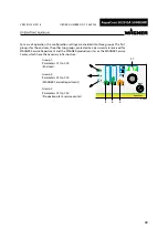
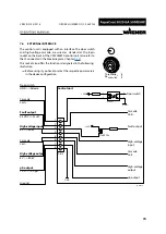
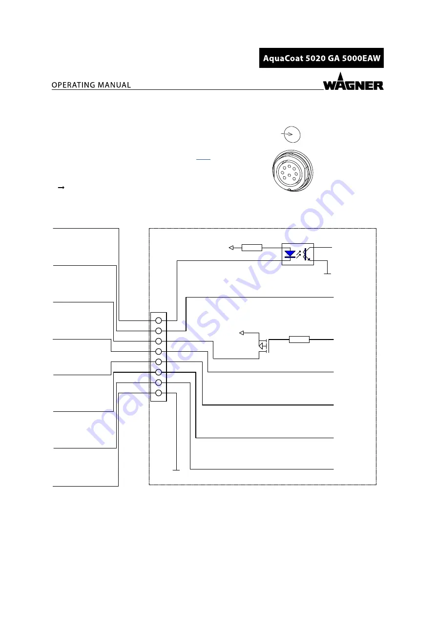
The control unit is equipped with an interface. The door switch
and high-voltage cascade are wired as standard at the 8-pin
socket on the back of the VM 5020WA control unit (also refer to
the J3 connector in the block diagram, Chapter
This socket also offers the functions designated in the following
illustration.
Türschalter
Door switch
B_05902
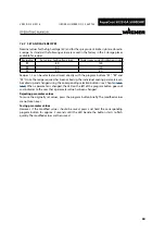
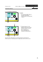
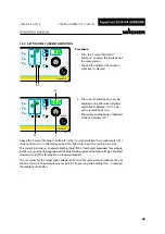
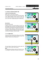
Before using it, you have to select the respective parameters
in the device configuration.
1
2
3
4
1
2
3
4
5
6
7
8
B_03415
+24V
DIN8
STN3PF06
LTV357
GND
GND
+24V
Control unit
Door switch
Cascade
Coil +
Fault output
High-voltage
input
µA output
Door switch
Cascade
GND >> Release
Coil +
Fault output
24 VDC >> Fault
High-voltage input
8 V >> 80 kV
Cascade
Coil -
High-voltage output
8 V >> 80 kV
µA output
10 V >> 100 µA
Ground
Cascade
Coil -
High-voltage
output

